Component replacement procedures
This chapter provides removal and replacement procedures.
There are as many as 33 screws, in 5 different sizes, that must be removed, replaced, or loosened
when servicing the computer. Make special note of each screw size and location during removal and
replacement.
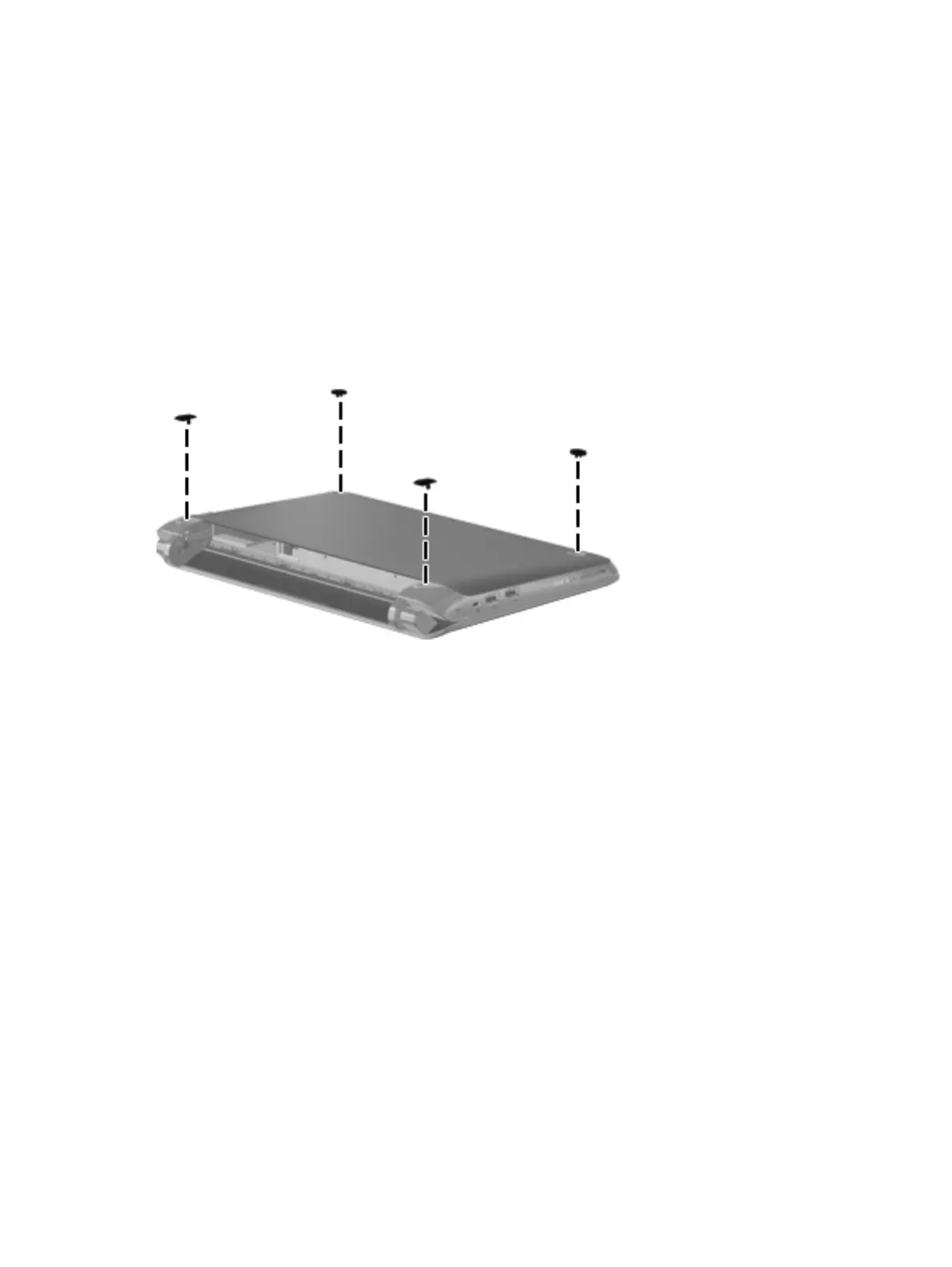
Computer feet
The computer feet are adhesive-backed rubber pads. The feet are included in the Rubber Feet Kit,
spare part number 636763-001. There are 4 rubber feet that attach to the base enclosure in the
locations shown in the following illustration.
34 Chapter 4 Removal and replacement procedures
Download from Www.Somanuals.com. All Manuals Search And Download.