When replacing the system board, be sure that the following components are removed from the
defective system board and installed on the replacement system board:
●
SIM (see
SIM on page 37)
●
WWAN module (see
WWAN and GPS modules (select models only) on page 43)
●
WLAN module (see
WLAN module on page 45)
●
Memory module (see
Memory module on page 47)
●
RTC battery (see
RTC battery on page 48)
●
Fan/heat sink assembly (see
Fan/heat sink assembly on page 64)
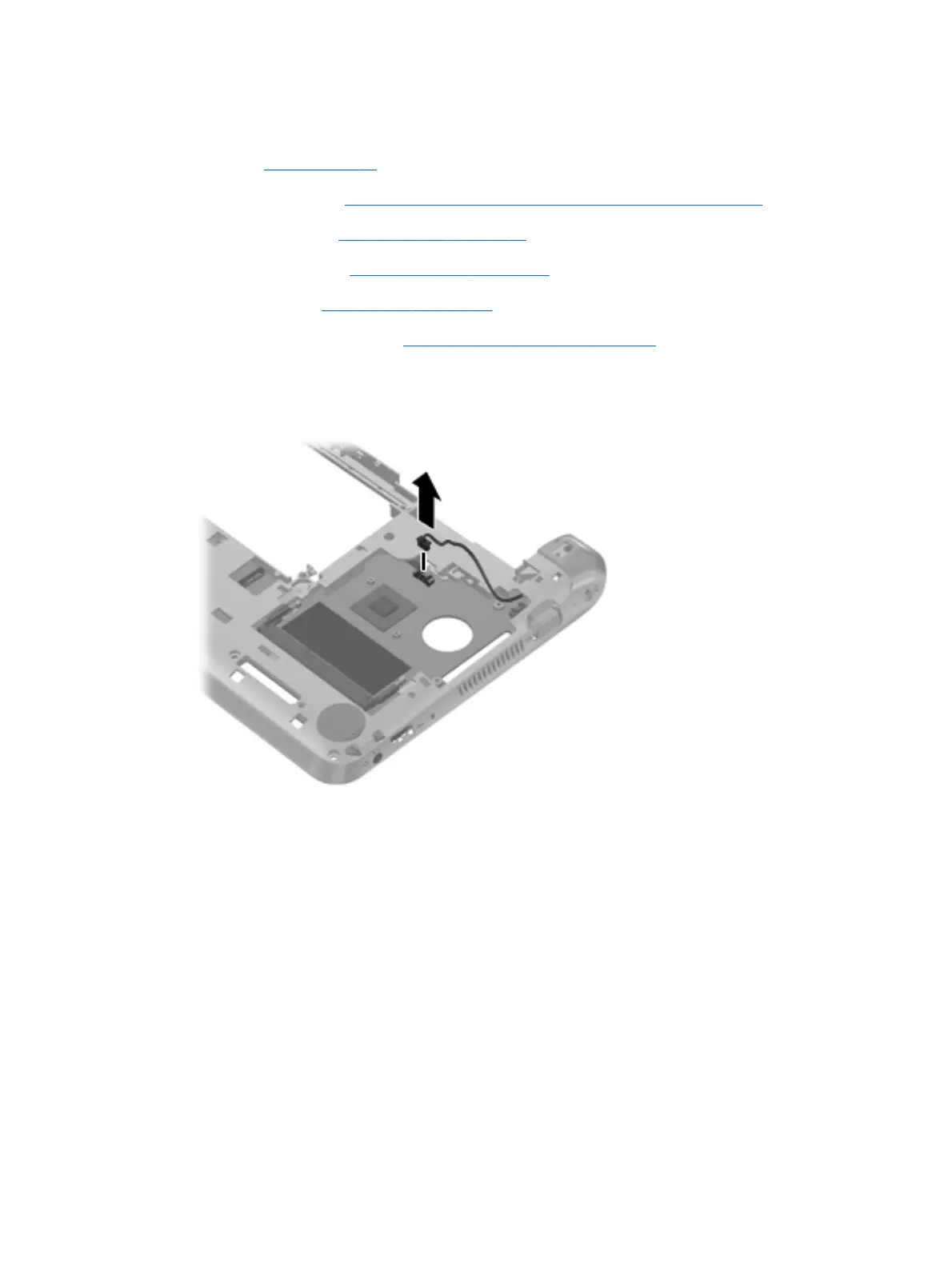
Remove the system board:
1. Disconnect the power connector cable from the system board.
2. Remove the 2 Phillips 2.0×4.0 screws (1) that secure the system board to the base enclosure.
3. Lift the right side of the system board (2) until it rests at an angle.
Component replacement procedures
67
Download from Www.Somanuals.com. All Manuals Search And Download.