EasyManuals Logo

HP MINI 5103 Maintenance And Service Guide

HP MINI 5103
139 pages
To Next Page IconTo Next Page
To Previous Page IconTo Previous Page
Page #76 background imageLoading...
Page #76 background image
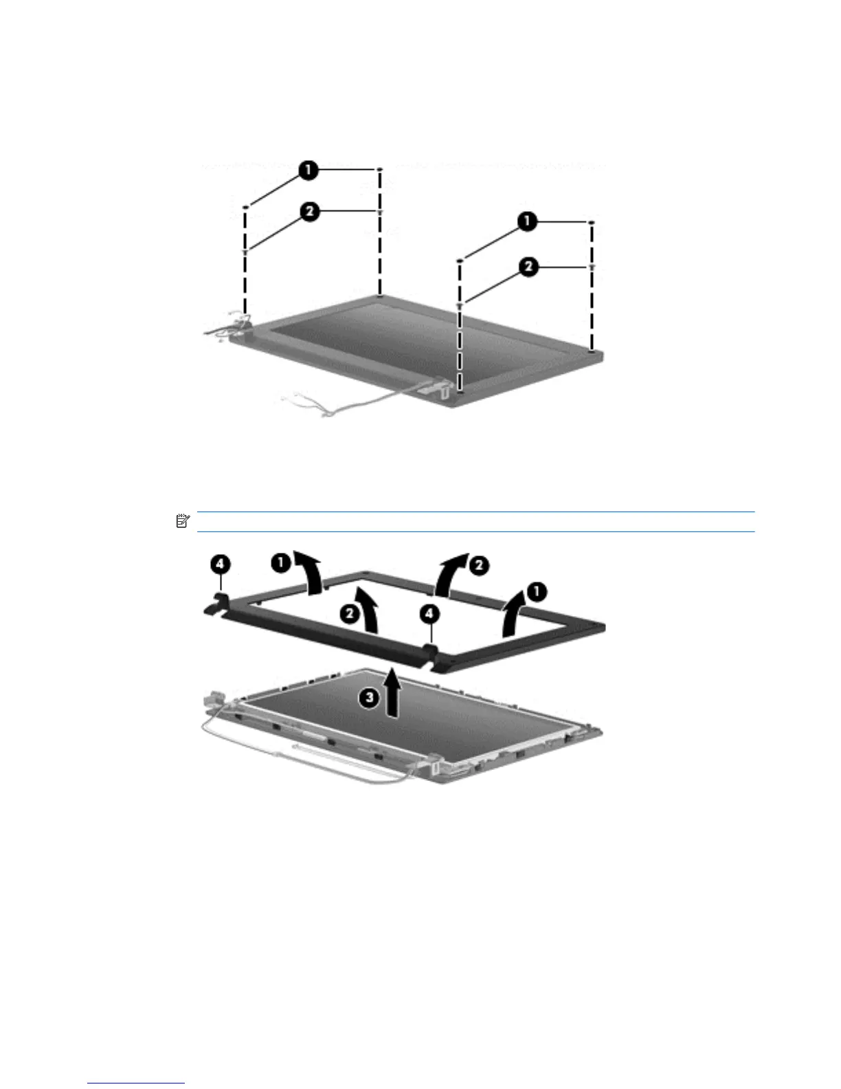
4. To replace the display bezel:
a. Remove the 4 Mylar screw covers (1) from the corners of the display bezel, and then
remove the 4 2.5×3.0 screws (2) that secure the display bezel to the back cover.
b. Flex the inside edges of the left and right sides (1), and then the top and bottom (2) of the
display bezel until the bezel disengages from the display enclosure.
c. Remove the display bezel (3).
NOTE: Tabs on the hinge covers (4) lock to insets on the base enclosure.
5. To replace the webcam module:
a. Lift the webcam (1).
68 Chapter 4 Removal and replacement procedures

Table of Contents

Other manuals for HP MINI 5103

Questions and Answers:

Question and Answer IconNeed help?

Do you have a question about the HP MINI 5103 and is the answer not in the manual?

HP MINI 5103 Specifications

General IconGeneral
GraphicsIntel GMA 3150
WebcamIntegrated 2 MP webcam
ProcessorIntel Atom N455 (1.66 GHz), Intel Atom N475 (1.83 GHz)
Display10.1-inch diagonal LED-backlit HD (1366 x 768)
RAMUp to 2 GB DDR3
Storage160 GB HDD
Operating SystemWindows 7 Starter
Battery3-cell or 6-cell Lithium-Ion battery
Weight2.64 lbs (1.2 kg)
Dimensions10.3 x 7.1 x 0.9 inches
Wireless802.11b/g/n
Ports3 x USB 2.0, VGA
Card ReaderSD/MMC
Keyboard95% full-size

Related product manuals