129
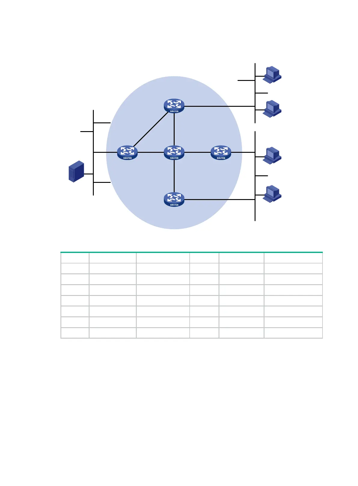
IGMPv2 runs between Router A and N1, and between Router B, Router C, and N2.
Figure 45 Network diagram
Table 9 Interface and IP address assignment
Router A GE1/0/1 10.110.1.1/24 Router D GE1/0/1 10.110.5.1/24
Router A GE1/0/2 192.168.1.1/24 Router D GE1/0/2 192.168.1.2/24
Router A GE1/0/3 192.168.9.1/24 Router D GE1/0/3 192.168.4.2/24
Router B GE1/0/1 10.110.2.1/24 Router E GE1/0/1 192.168.3.2/24
Router B GE1/0/2 192.168.2.1/24 Router E GE1/0/2 192.168.2.2/24
Router C GE1/0/1 10.110.2.2/24 Router E GE1/0/3 192.168.9.2/24
Router C GE1/0/2 192.168.3.1/24 Router E GE1/0/4 192.168.4.1/24
Configuration procedure
1. Assign an IP address and subnet mask to each interface, as shown in Figure 45. (Details not
shown.)
2. Configure OSPF on all routers in the PIM-SM domain. (Details not shown.)
3. Enable IP multicast routing, IGMP and PIM-SM:
# On Router A, enable IP multicast routing.
<RouterA> system-view
[RouterA] multicast routing
[RouterA-mrib] quit
# Enable IGMP on the receiver-side interface (GigabitEthernet 1/0/1).
[RouterA] interface gigabitethernet 1/0/1
Ethernet
EthernetEthernet
Source
10.110.5.100/24
PIM-SM
Router A
Router B
Router C
Router D
Receiver
Host A
Host B
Host C
Host D
Receiver
N1N2
Router E
GE1/0/1
GE1/0/1
GE1/0/1
GE1/0/1
GE1/0/3
GE1/0/3
GE1/0/2GE1/0/2
GE1/0/2
GE1/0/2
GE1/0/2
GE1/0/1
GE1/0/4
GE1/0/3
 Loading...


