202
IP multicast routing
• Enable IP multicast routing on the P router.
• Enable IP multicast routing on the public network instance on PE 1,
PE 2, and PE 3.
• Enable IP multicast routing for VPN instance a on PE 1, PE 2, and PE
3.
• Enable IP multicast routing for VPN instance b on PE 2 and PE 3.
•
Enable IP multicast routing on CE a1, CE a2, CE a3, CE b1, and CE
b2.
IGMP
• Enable IGMPv2 on GigabitEthernet 1/0/2 of PE 1.
• Enable IGMPv2 on GigabitEthernet 1/0/1 of CE a2, CE a3, and CE b2.
PIM
Enable PIM-SM on the public network and for VPN instances
a
and
b
:
• Enable PIM-SM on all interfaces of the P router.
• Enable PIM-SM on all public and private network interfaces on PE 1,
PE 2, and PE 3.
• Enable PIM-SM on all interfaces that do not have attached receiver
hosts on CE a1, CE a2, CE a3, CE b1, and CE b2.
• Configure Loopback 1 of P as a public network C-BSR and C-RP to
provide services for all multicast groups.
• Configure Loopback 1 of CE a2 as a C-BSR and a C-RP for VPN
instance a to provide services for all multicast groups.
• Configure Loopback 2 of PE 3 as a C-BSR and a C-RP for VPN
instance b to provide services for all multicast groups.
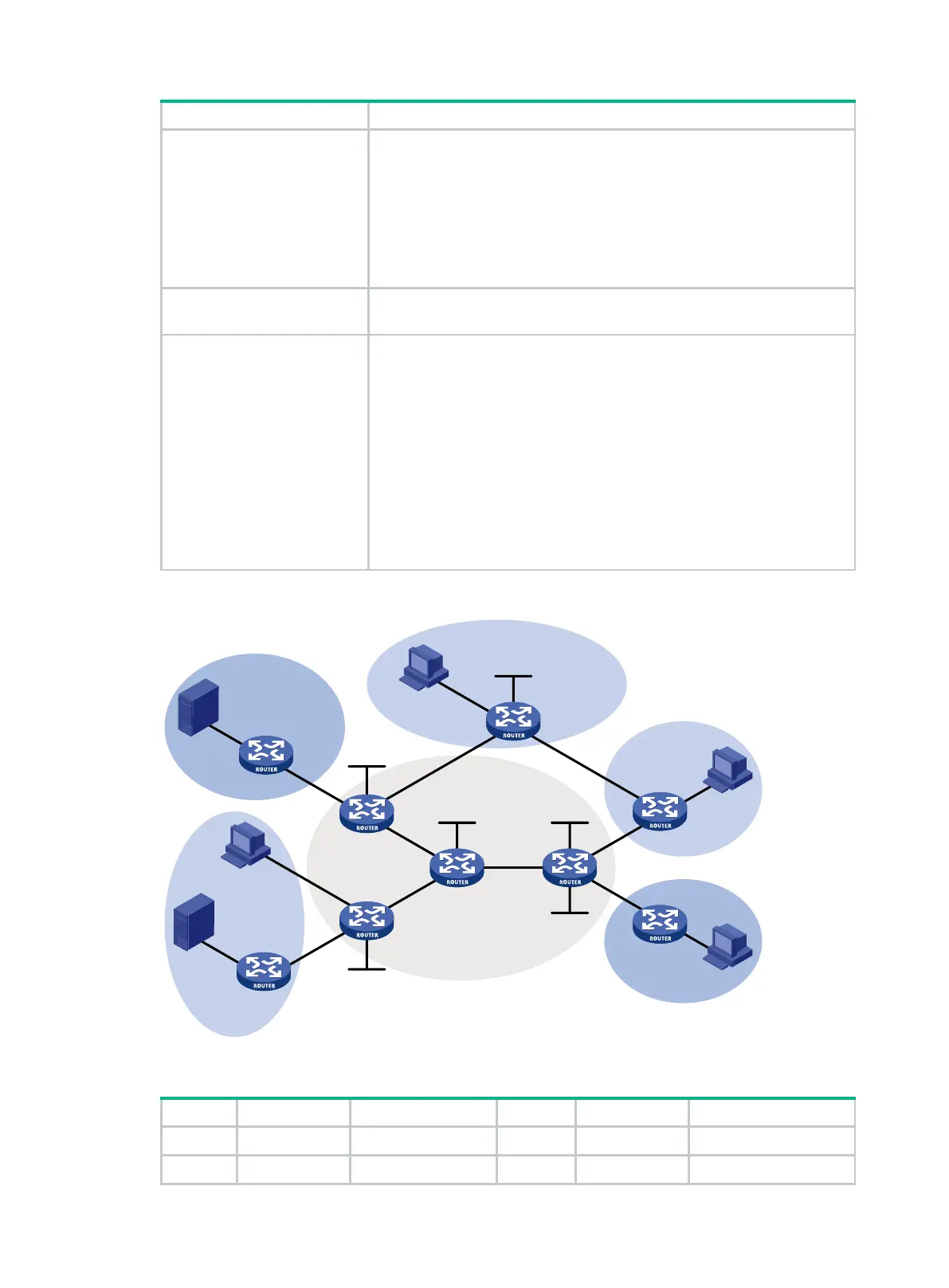
Figure 71 Network diagram
Table 18 Interface and IP address assignment
S 1 — 10.110.7.2/24 PE 3 GE1/0/1 192.168.8.1/24
S 2 — 10.110.8.2/24 PE 3 GE1/0/2 10.110.5.1/24
GE1/0/3
GE1/0/1
Loop1
Loop1
Loop1
Loop1
Loop2
Loop1
GE1/0/1
GE1/0/2
GE1/0/1
GE1/0/2
GE1/0/3
GE1/0/1
GE1/0/1
GE1/0/3
GE1/0/2
GE1/0/1
GE1/0/2
GE1/0/2
GE1/0/2
GE1/0/3
GE1/0/2
GE1/0/1
GE1/0/1
GE1/0/1
GE1/0/2
GE1/0/3
S 2
S 1
P
PE 1
PE 2
PE 3
GE1
/0/2
CE a1
CE a2
CE a3
CE b1
CE b2
Public
VPN b
VPN b
VPN a
VPN a
VPN a
GE1/0/3
R 1
R 2
R 3
R 4
 Loading...


