56
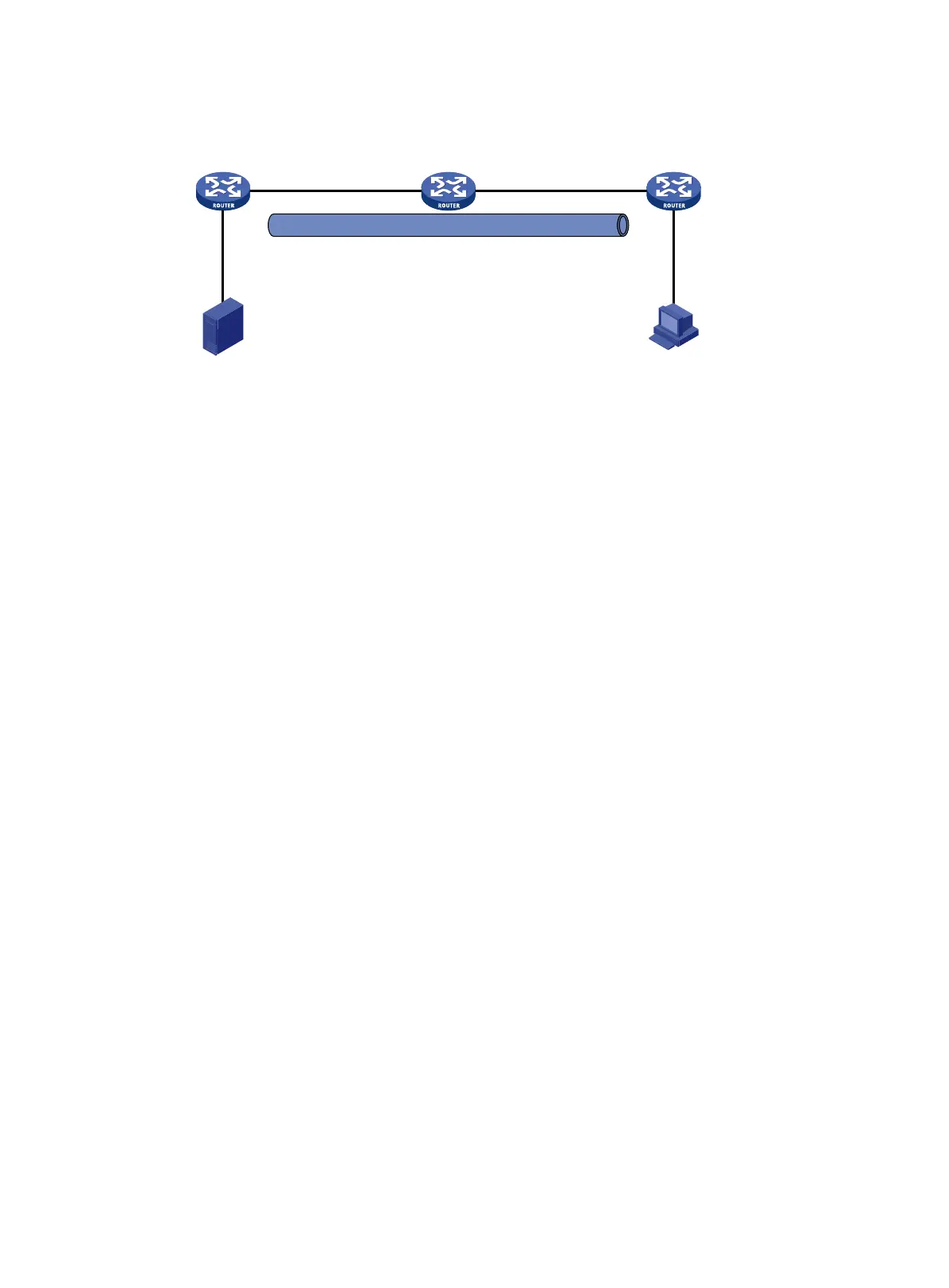
Figure 21 Network diagram
Configuration procedure
1. Assign an IP address and mask for each interface, as shown in Figure 21. (Details not shown.)
2. Configure OSPF on all the routers. Do not enable OSPF on GigabitEthernet 1/0/1 on Router A.
(Details not shown.)
3. Configure a GRE tunnel:
# Create a GRE tunnel interface Tunnel 0 on Router A, and specify the tunnel mode as
GRE/IPv4.
<RouterA> system-view
[RouterA] interface tunnel 0 mode gre
# Assign an IP address to interface Tunnel 0, and specify its source and destination addresses.
[RouterA-Tunnel0] ip address 50.1.1.1 24
[RouterA-Tunnel0] source 20.1.1.1
[RouterA-Tunnel0] destination 30.1.1.2
[RouterA-Tunnel0] quit
# Create a GRE tunnel interface Tunnel 0 on Router C, and specify the tunnel mode as
GRE/IPv4.
<RouterC> system-view
[RouterC] interface tunnel 0 mode gre
# Assign an IP address to interface Tunnel 0, and specify its source and destination addresses.
[RouterC-Tunnel0] ip address 50.1.1.2 24
[RouterC-Tunnel0] source 30.1.1.2
[RouterC-Tunnel0] destination 20.1.1.1
[RouterC-Tunnel0] quit
4. Enable IP multicast routing, PIM-DM, and IGMP:
# On Router A, enable IP multicast routing.
[RouterA] multicast routing
[RouterA-mrib] quit
# Enable PIM-DM on each interface.
[RouterA] interface gigabitethernet 1/0/1
[RouterA-GigabitEthernet1/0/1] pim dm
[RouterA-GigabitEthernet1/0/1] quit
[RouterA] interface gigabitethernet 1/0/2
[RouterA-GigabitEthernet1/0/2] pim dm
[RouterA-GigabitEthernet1/0/2] quit
Multicast router
Router A
GE1/0/2
20.1.1.1/24
GE1/0/2
30.1.1.1/24
GE1/0/2
30.1.1.2/24
GE1/0/1
20.1.1.2/24
Source Receiver
40.1.1.100/24
GE1/0/1
40.1.1.1/24
10.1.1.100/24
GE1/0/1
10.1.1.1/24
GRE tunnel
Tunnel0
50.1.1.1/24
Tunnel0
50.1.1.2/24
Unicast router
Router B
Multicast router
Router C
 Loading...


