Network connector door
Table 6-8 Network connector door description and part number
Description Spare part number
Network connector door L57023-001
Before removing the network connector door, follow these steps:
1. Prepare the computer for disassembly (Preparation for disassembly on page 26).
2. Remove the bottom cover (see Bottom cover on page 27).
3. Remove the battery (see Battery and speakers on page 32).
4. Remove the solid-state drive (see Solid-state drive and Optane Memory Module on page 29).
5. Remove the heat sink/fan assembly (see Heat sink/fan assembly on page 35).
6. Remove the second display transfer board (see Second display transfer board on page 38).
7. Remove the power connector board and bracket (see Power connector cable on page 39).
8. Remove the system board (see System board on page 41).
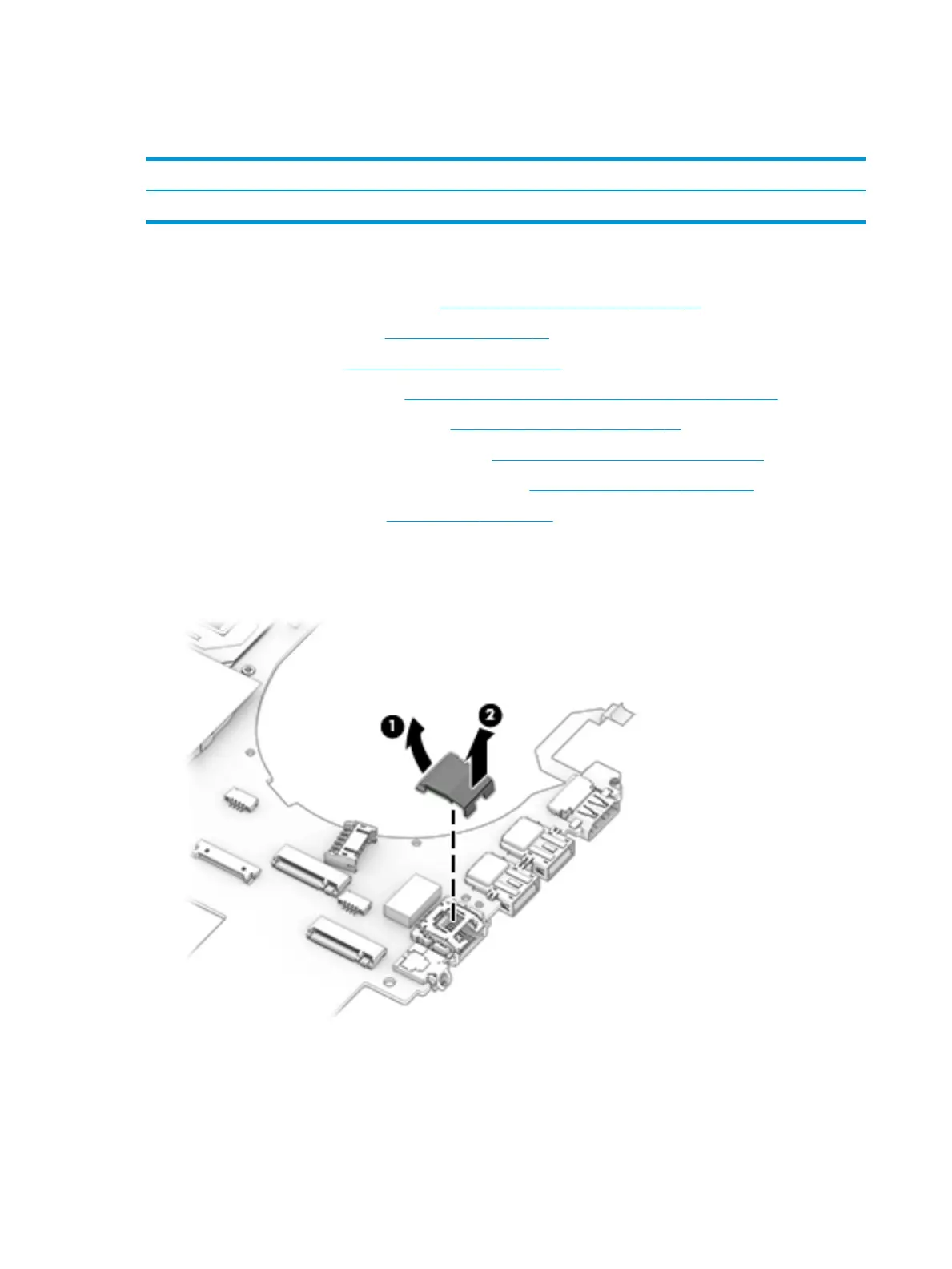
Remove the network connector door:
▲ From the removed system board, lift the back of the door (1), and then remove the door from the
computer (2).
Reverse this procedure to install the network connector door.
44 Chapter 6 Removal and replacement procedures for authorized service provider parts