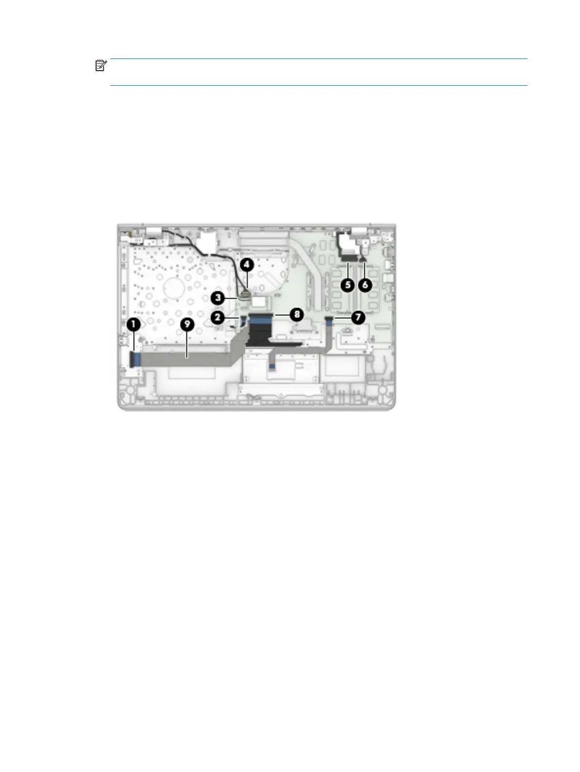
NOTE: The #1/white wireless antenna cable connects to the WLAN module "#1/Main" terminal. The
#2/ black wireless antenna cable connects to the WLAN module "#2/Aux" terminal.
(4) Power connector cable
(5) Display panel ZIF connector cable
(6) Speaker cable
(7) TouchPad ZIF connector cable
(8) Keyboard ZIF connector cable
2. Detach the connector board cable (9) from the keyboard/top cover. (The connector board cable is
attached to the keyboard/top cover with double-sided adhesive.)
3. Remove the nine Phillips PM2.0×4.2 screws (1) that secure the system board to the keyboard/top cover.
38 Chapter 5 Removal and replacement procedures
 Loading...