Removal and Replacement Procedures
Maintenance and Service Guide 5–67
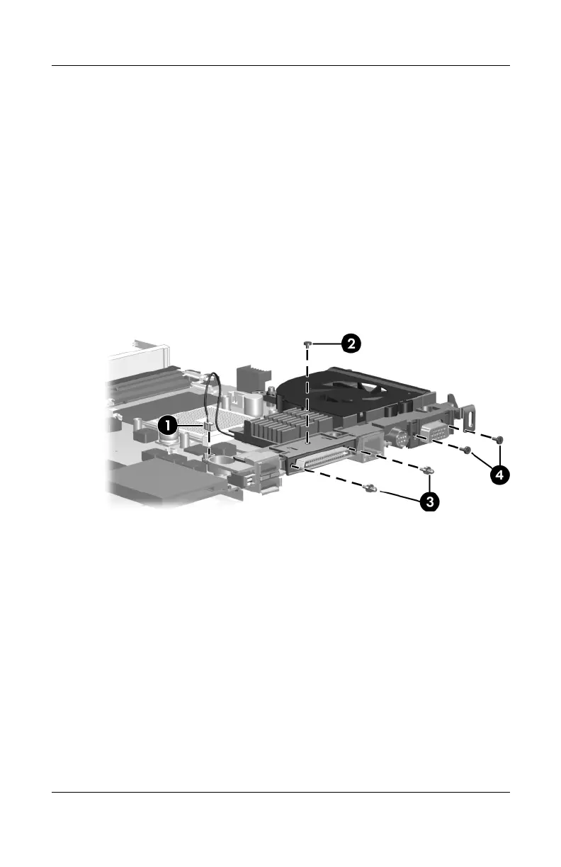
2. Disconnect the fan cable 1 from the system board.
3. Remove the following screws:
2 One Phillips PM2.5×3.0 screw that secures the expansion
port 2 bracket to the system board
3 Two slotted M1.5×9.0 screws on each side of the
expansion port 2 connector that secure the expansion
port 2 bracket to the system board
4 Two Phillips PM3.0×6.0 screws on each side of the
external monitor connector that secure the fan assembly
to the system board
Removing the Fan Assembly Screws
Download from Www.Somanuals.com. All Manuals Search And Download.
 Loading...