4. Remove the battery (see Battery on page 41).
5. Remove the following components:
a. Hard drive (see
Hard drive on page 46)
b. Optical drive (see
Optical drive on page 54)
c. Switch cover (see
Switch cover on page 56)
d. Keyboard (see
Keyboard on page 60)
e. Speaker assembly (see
Speaker assembly on page 58)
f. Display assembly (see
Display assembly on page 63)
g. Top cover (see
Top cover on page 69)
h. Audio board (see
Audio board on page 80)
i. USB/power connector board (see
USB/power connector board on page 76)
j. System board (see
System board on page 77)
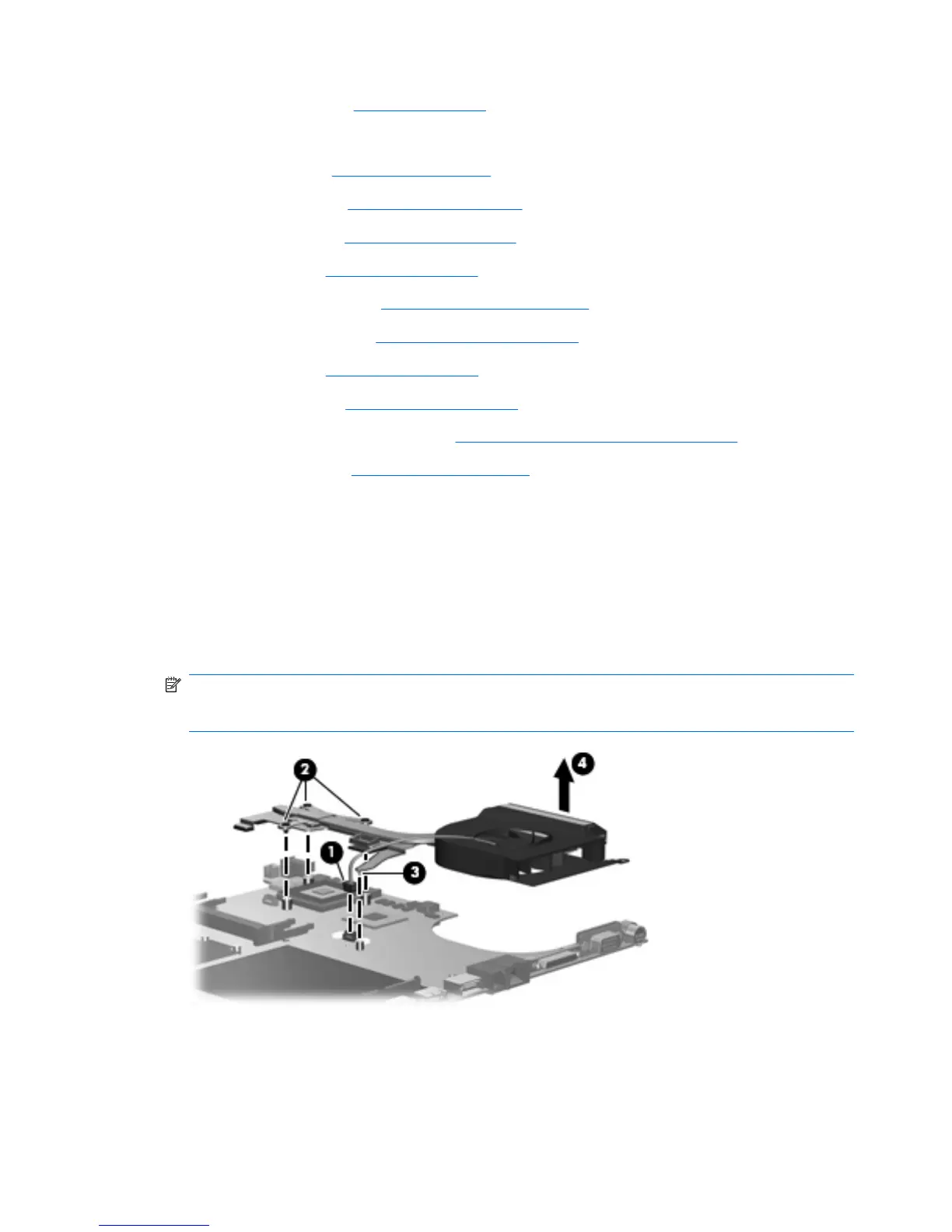
Remove the fan/heat sink assembly:
1. Turn the system board upside down with the expansion port 3 and external monitor port toward you.
2. Disconnect the fan cable (1) from the system board.
3. Loosen the three Phillips PM2.5×5.0 screws (2) and the Phillips PM2.5×4.0 screw (3) that secure
the fan/heat sink assembly to the system board.
4. Remove the fan/heat sink assembly (4).
NOTE: Due to the adhesive quality of the thermal paste and thermal pads located between the
fan/heat sink assembly and system board components, it may be necessary to move the fan/heat
sink assembly from side to side to detach the assembly.
82 Chapter 4 Removal and replacement procedures