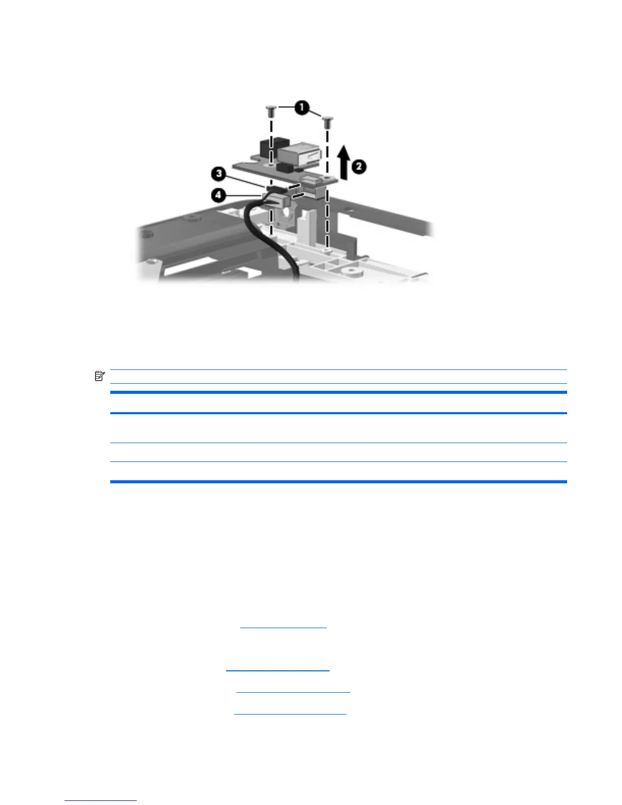
3. Disconnect the USB cable (3) and the power connector cable (4) from the USB/power connector
board.
4. Remove the USB/power connector board.
Reverse this procedure to install the USB/power connector board.
System board
NOTE: All system board spare part kits include a modem cable and replacment thermal material.
Description Spare part number
For use only with computer models equipped with discrete graphics subsystem memory (includes 128
MB of discrete graphics subsystem memory)
446476-001
For use only with full-featured computer models equipped with UMA graphics subsystem memory 446477-001
For use only with defeatured computer models equipped with UMA graphics subsystem memory 453769-001
Before removing the system board, follow these steps:
1. Shut down the computer. If you are unsure whether the computer is off or in Hibernation, turn the
computer on, and then shut it down through the operating system.
2. Disconnect all external devices connected to the computer.
3. Disconnect the power from the computer by first unplugging the power cord from the AC outlet and
then unplugging the AC adapter from the computer.
4.
Remove the battery (see
Battery on page 41).
5. Remove the following components:
a. Hard drive (see
Hard drive on page 46)
b. Optical drive (see
Optical drive on page 54)
c. Switch cover (see
Switch cover on page 56)
Component replacement procedures 77