2-4
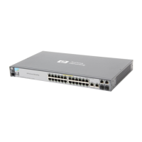
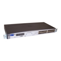
Installing the Switch 2124
Installation Procedures
Installing the Switch 2124
1. Prepare the Installation Site
■ Cabling Infrastructure - Ensure that the cabling infrastructure meets
the necessary network specifications. See the following table for cable
types and lengths, and see appendix B, “Switch Ports and Network
Cables” for more information:
Table 2-1. Summary of Cable Types to Use with the Switch
■ Installation Location - Before installing the switch, plan its location and
orientation relative to other devices and equipment:
• At the front of the switch, leave at least 7.6 cm (3 inches) of space for
the twisted-pair and fiber-optic cabling.
• At the back of the switch, leave at least 7.6 cm (3 inches) of space for
the power cord and cooling.
• On the sides of the switch, leave at least 3.8 cm (1 1/2 inches) for
cooling.
Port Type Cable Type Length Limits
10/100Base-TX • 10 Mbps operation:
Category 3, 4, or 5, 100-ohm differential
unshielded twisted-pair (UTP) or shielded
twisted-pair (STP).
• 100 Mbps operation:
Category 5, 100-ohm differential UTP or
STP.
100 meters.
Note: Since the 10Base-T operation is through
10/100Base-TX ports, if you ever want to upgrade
the ports to 100Base-TX, it would be best to cable
the ports initially with category 5 cable.
The 10/100-Base-TX ports on the Switch 2124
include the”HP Auto-MDIX” feature, which allows
you to use either straight-through or crossover
twisted-pair cables for connecting to any network
devices including end nodes, such as computers,
or to other switches, hubs, and routers.
100Base-FX
for transceiver
connection
62.5/125 ←m or 50/125 ←m (core/cladding)
diameter, graded-index, multimode fiber-
optic cables, complying with the ITU-T G.651
and ISO/IEC 793-2 Type A1b or A1a
respectively, fitted with SC connectors.
2 kilometers for full-duplex connections.
(When installed in a Switch 2124, the HP 100-FX SC
Transceiver operates only in full-duplex mode.)
 Loading...