15
Switch Installation
Example Topologies
The following illustrations are examples of typical, supported configurations for an HP
BladeSystem c3000 and BladeSystem c7000 Enclosure.
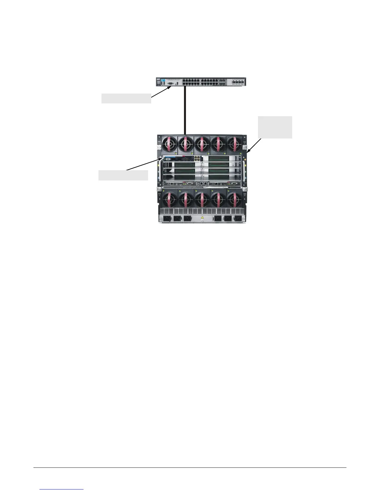
Figure 10. Example single point topology
This illustration shows the most basic of configurations. A single switch in each location (top
of rack and in the Server) provides connectivity through the RJ-45 connections, through the
mini-GBIC fiber connections, or through the XFP/SFP+ Direct Attach cable.
It is recommended to use only HP/ProCurve Direct Attach cables. If a non-HP/ProCurve Direct
Attach cable is used and the topology does not work, HP support may require an HP/ProCurve
Direct Attach cable be installed for troubleshooting.
There is no redundancy in this configuration, however redundancy can be built in by adding
m
ore than one type or speed of connectivity. For example connecting to the RJ-45 ports on the
6120G/XG and cabling to the RJ-45 ports on the Top of rack switch. Then by connecting the
mini-GBIC fiber connections from one switch to the other multiple paths can be made through
which data can pass.
In the same way the two switches can be connected through the XFP/SFP+ Direct Attach cable
to gain the 10-GbE speed.
Top of rack switch
Server with one
6120G/XG
Blade Switch
6120G/XG Blade Switch

 Loading...


