EL-MF877-00 Page 3
Template Revision C
Last revalidation date 09-May-2018
HPI instructions for this template are available at EL-MF877-01
25. Use PH1 screwdriver to loose the screws and remove the SSD from the board.
26. Use T-15 screwdriver to loose the screws of MB from board.
27. Remove speaker from Chassis.
28. Remove MB from chassis.
29. Use T-15 screwdriver remove the screws on the PSU chassis.
30. Press the PSU latch on chassis.
31. Remove the PSU from chassis.
32. Use PH1 screwdriver to remove screw for the PSU.
33. Remove PSU cover.
34. Use PH1 screwdriver to remove FG screw.
35. Disconnect fan connector and inlet connector.
36. Loose screws and remove PCA from case.
37. Use PH1 screwdriver to remove AC inlet & Fan screw.
38. Heat the solder of the Electrolytic Capacitors of greater than 2.5cm in diameter or height and remove it.
3.2 Optional Graphic. If the disassembly process is complex, insert a graphic illustration below to identify the items
contained in the product that require selective treatment (with descriptions and arrows identifying locations).
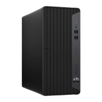
Step1 Use T-15 screwdriver to Loose thumb screw and
remove access panel
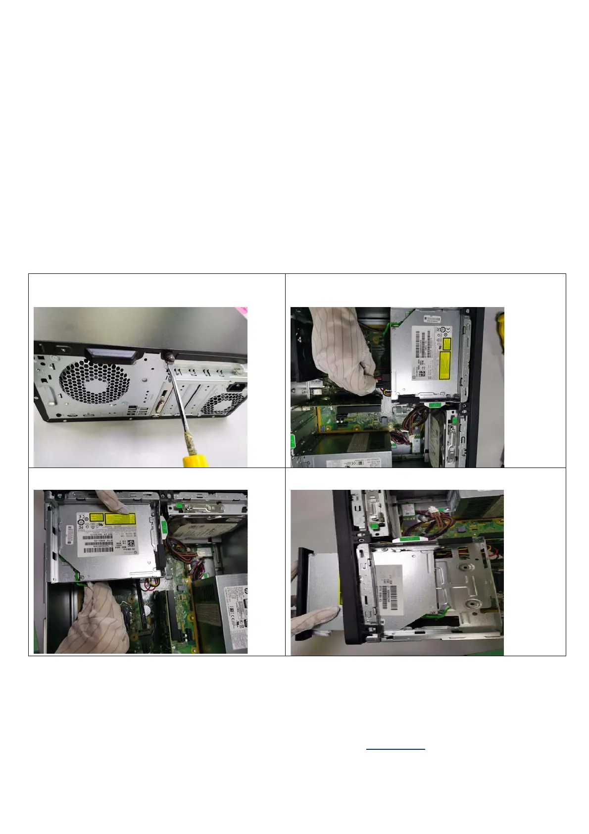
Step2 Disconnect ODD power cable and ODD SATA cable
from ODD
Step3 Press the ODD’s latch on ODD cage
Step4 Remove the ODD from ODD cage
 Loading...