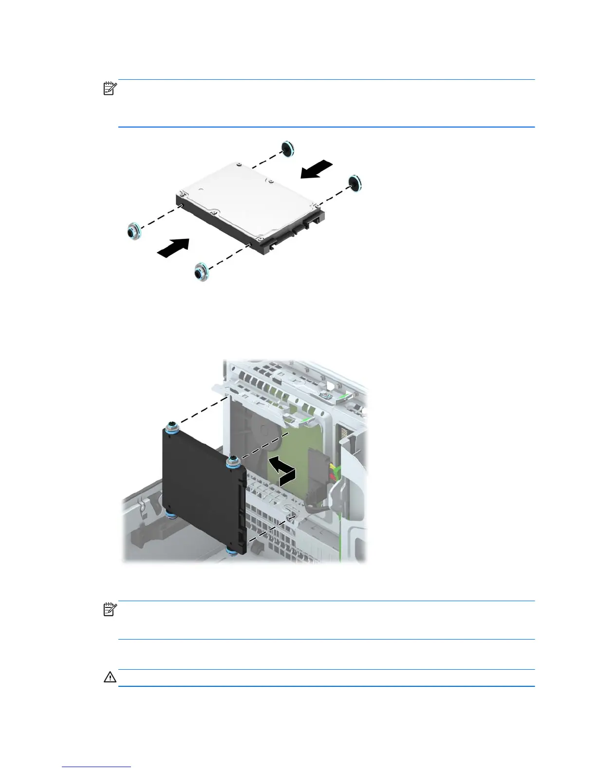
4. Install four black and blue M3 isolation mounting guide screws (two on each side of the drive).
NOTE: M3 metric isolation mounting guide screws can be purchased from HP.
When replacing a drive, transfer the four M3 isolation mounting guide screws from the old drive
to the new one.
5. Rotate the drive cage to its upright position.
6. Align the guide screws on the drive with the J-slots on the sides of the drive bay. Press the drive up
into the drive bay then slide it forward until it locks in place.
7. Connect the power cable and data cable to the back of the hard drive.
NOTE: If the 2.5-inch hard drive is the primary drive, connect the data cable to the dark blue
SATA connector labeled SATA0 on the system board. If it is a secondary drive, connect the data
cable to one of the light blue SATA connectors on the system board.
8. Rotate the drive cage back down to its normal position.
CAUTION: Be careful not to pinch any cables or wires when rotating the drive cage down.
110 Chapter 6 Removal and replacement procedures: Small Form Factor (SFF)
 Loading...