System board
The system board is secured with three screws.
To remove the system board:
1. Prepare the computer for disassembly (see Preparing to disassemble the computer on page 19).
2. Remove the stand (see Stand on page 19).
3. Remove the rear port cover (see Rear port cover on page 24).
4. Remove the fan (see Fan assembly on page 36).
5. Remove the heat sink (see Heat sink on page 37).
6. When replacing the system board, make sure the following components are removed from the defective
system board and installed on the replacement system board:
● Memory modules (Memory on page 30)
● M.2 solid-state drive (M.2 solid-state drive on page 29)
● WLAN module (WLAN module on page 33)
● Processor (Processor on page 39)
● Option board (Option board on page 34)
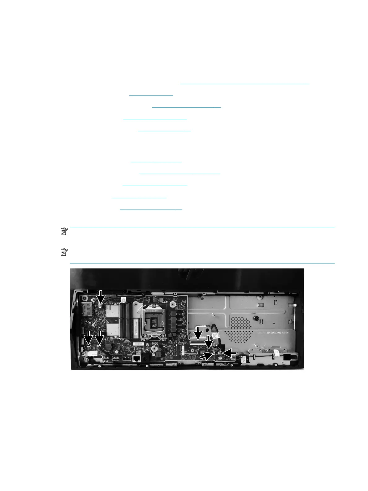
7. Disconnect all cables from the system board, noting their location for reinstallation.
NOTE: If replacing the system board, you do not need to disconnect the RTC battery, as replacement
boards come with a battery already connected.
NOTE: Additional cables may be connected to the system board. The following illustration shows the
most likely connected cables.
8. Remove the three screws (1) that secure the system board to the computer.
9. Lift the right side of the system board up slightly (2).
40 Chapter 4 Removal and Replacement Procedures
 Loading...