21
2) Use a hot air gun to melt the solder on the pins.
3) Lift the J3 connector from the PCB.
4) Place the new component on the PCB. Be sure that it matches the PCB footprint.
5) Solder the new component.
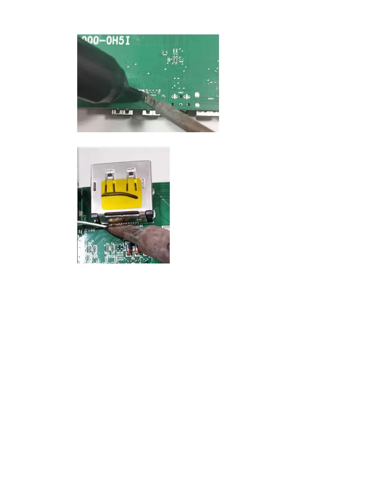
USB connector J4
Before removing the USB connector, follow these steps:
▲ Prepare the monitor for disassembly. See Preparation for disassembly on page 13.
Remove the USB connector:
1. Use a hot air gun to melt the solder on the pins. Pin solder with soldering iron and absorber. You
can gently push down with the soldering iron once everything is molten to move the J4 out of the
through holes.
 Loading...