EasyManua.ls Logo

HPE Apollo 2000 Gen10 Plus System - User Manual

HPE Apollo 2000 Gen10 Plus System
8 pages
Print Icon
To Next Page IconTo Next Page
Loading...
MF877-00 Page 1
Template Revision C, 30-July-2018
Copyright 2018 Hewlett Packard Enterprise Development LP
HPE instructions for this template are available at MF877-01
Product End-of-Life Disassembly Instructions
Product Category
: Servers
Marketing Name / Model
[List multiple models if applicable.]
HPE Apollo 2000 Gen10 Plus System
HPE Apollo n2400 Gen10 Plus SFF CTO Chassis
HPE Apollo n2600 Gen10 Plus SFF CTO Chassis
HPE Apollo n2800 Gen10 Plus SFF CTO Chassis
Purpose: The document is intended for use by end-of-life recyclers or treatment facilities. It provides the basic instructions
for the disassembly of HPE products to remove components and materials requiring selective treatment, as defined by
Directive 2012/19/EU of the European Parliament and of the Council on Waste Electrical and Electronic Equipment
(WEEE).
1.0 Items Requiring Selective Treatment
1.1 Items listed below are classified as requiring selective treatment.
1.2 Enter the quantity of items contained within the product which require selective treatment in the right column, as
applicable.
Item Description Notes
Quantity
of items
included
in product
Printed Circuit Boards (PCB) or Printed Circuit
Assemblies (PCA)
With a surface greater than 10 sq cm
15
Batteries
All types including standard alkaline and lithium
coin or button style batteries
1
Mercury-containing components
For example, mercury in lamps, display backlights,
scanner lamps, switches, batteries
0
Liquid Crystal Displays (LCD) with a surface
greater than 100 sq cm
Includes background illuminated displays with gas
discharge lamps
0
Cathode Ray Tubes (CRT)
0
Capacitors / condensers (Containing PCB/PCT)
0
Electrolytic Capacitors / Condensers measuring
greater than 2.5 cm in diameter or height
Depending on Power Supply
7
External electrical cables and cords
0
Gas Discharge Lamps
0
Plastics containing Brominated Flame Retardants
weighing > 25 grams (not including PCBs or PCAs
already listed as a separate item above)
There’s no containing Brominated Flame
Retardants
0
Components and parts containing toner and ink,
including liquids, semi-liquids (gel/paste) and toner
Include the cartridges, print heads, tubes, vent
chambers, and service stations.
0
Question and Answer IconNeed help?

Do you have a question about the HPE Apollo 2000 Gen10 Plus System and is the answer not in the manual?

Summary

Items Requiring Selective Treatment

Tools Required

Product Disassembly Process

Summary

Items Requiring Selective Treatment

Tools Required

Product Disassembly Process

Overview

This document outlines the end-of-life disassembly instructions for specific HPE Apollo server systems, focusing on the removal of components and materials requiring selective treatment as per Directive 2012/19/EU (WEEE). The primary function of this guide is to provide a clear, step-by-step process for recyclers and treatment facilities to ensure environmentally responsible disposal and material recovery from these server products.

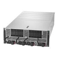
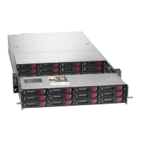
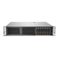
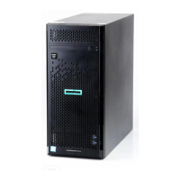
The targeted server models include the HPE Apollo 2000 Gen10 Plus System, HPE Apollo n2400 Gen10 Plus SFF CTO Chassis, HPE Apollo n2600 Gen10 Plus SFF CTO Chassis, and HPE Apollo n2800 Gen10 Plus SFF CTO Chassis. These systems are designed for high-performance computing and data center environments, offering robust capabilities for various enterprise workloads.

Usage Features:

The core usage feature of this document is its utility as a practical guide for disassembly. It categorizes items requiring selective treatment, providing a comprehensive list that includes:

  • Printed Circuit Boards (PCBs) or Printed Circuit Assemblies (PCAs): These are identified as components with a surface greater than 10 sq cm. The document specifies that there are 15 such items within the product, highlighting their significant presence and the need for careful handling. PCBs and PCAs are critical for the electronic functionality of the servers, containing various integrated circuits, connectors, and other electronic components. Their selective treatment is crucial due to the potential presence of hazardous materials and valuable metals.
  • Batteries: This category encompasses all types, including standard alkaline and lithium coin or button style batteries. The document indicates the presence of 1 battery, emphasizing the importance of its removal due to potential environmental hazards and the value of recoverable materials. Batteries are essential for maintaining system settings and providing backup power for certain functions.
  • Mercury-containing components: Examples provided include mercury in lamps, display backlights, scanner lamps, and switches. The document explicitly states that there are no mercury-containing components in these specific server models, which simplifies the selective treatment process by eliminating a common hazardous material.
  • Liquid Crystal Displays (LCDs): This refers to displays with a surface greater than 100 sq cm, including those with background illumination from gas discharge lamps. Similar to mercury-containing components, the document indicates no LCDs of this size are present, further streamlining the disassembly process.
  • Cathode Ray Tubes (CRTs): The document confirms the absence of CRTs, which is expected for modern server systems that typically do not incorporate such display technologies.
  • Capacitors/condensers (containing PCB/PCT): The document states that there are no capacitors or condensers containing PCBs or PCTs, which are known hazardous substances.
  • Electrolytic Capacitors/Condensers: These are specifically identified if they measure greater than 2.5 cm in diameter or height. The quantity is listed as 7, with a note indicating that this depends on the power supply. These capacitors are crucial for power regulation and filtering within the server's power supply units. Their selective removal is important due to their size and potential for containing substances that require specific recycling processes.
  • External electrical cables and cords: The document indicates no external electrical cables or cords are present, implying that these are either integrated or not considered part of the core product for selective treatment purposes.
  • Gas Discharge Lamps: The document confirms the absence of gas discharge lamps, which aligns with the lack of large LCDs or other components that would typically use such lamps.
  • Plastics containing Brominated Flame Retardants (BFRs): This category specifically targets plastics weighing over 25 grams, excluding PCBs or PCAs already listed. The document states that there are no plastics containing BFRs in these products, which is a positive environmental feature, as BFRs are persistent organic pollutants.
  • Components and parts containing toner and ink: This includes cartridges, print heads, tubes, vent chambers, and service stations. The document indicates no such components are present, as these are server systems and not printing devices.

The document also specifies the tools required for disassembly: a screwdriver with T10/T15 sizes. This highlights the simplicity of the initial disassembly steps, requiring only common hand tools.

Maintenance Features (Disassembly Process):

The document provides a clear, three-step product disassembly process, designed to facilitate the removal of selective treatment items:

  1. PCA Removal: The first step instructs the user to "Remove all of PCAs with screwdriver." This is a fundamental step, as PCAs are numerous and contain a variety of materials requiring selective treatment. The use of a screwdriver suggests that these components are typically secured with standard fasteners.
  2. Megacell Module Removal: The second step details the removal of the Megacell Module. This involves removing the top cover of the system, locating the megacell, removing it, and disposing of it properly. The "proper disposal" instruction underscores the importance of following specific guidelines for this component, which may contain hazardous or valuable materials. Attachment 16 provides a visual aid for locating and removing the Megacell Module.
  3. Capacitor Removal (greater than 2.5 cm): The third step focuses on the removal of large capacitors. This involves removing the Node module from the chassis, then removing the node cover by pressing down a cover latch. Once the capacitors are located, a medium flat head screwdriver is used to remove them for proper disposal. This detailed instruction ensures that specific, potentially hazardous components are identified and handled correctly. Attachments 17-20 provide visual guidance for the location of super capacitors within the Power Supply Units (PSUs) for different models (HSTNS-PR62, HSTNS-PL62, 2200W HICKORY, and 3000W DIGGER), illustrating the specific capacitors to be removed.

The document includes numerous attachments (Attachment 1-15 for PCA Pictures, Attachment 16 for Megacell Module Location, and Attachment 17-20 for Super Cap Location in PSU) which serve as crucial visual aids. These graphics are essential for complex disassembly processes, helping to identify specific items and their locations within the product, thereby reducing ambiguity and ensuring accurate removal. The inclusion of HPPN (Hewlett Packard Part Number) for each illustrated PCA further aids in precise identification.

Overall, this document functions as a critical resource for ensuring that HPE Apollo server systems are disassembled in an environmentally sound manner at the end of their life cycle, promoting material recovery and minimizing ecological impact.

HPE Apollo 2000 Gen10 Plus System Specifications

General IconGeneral
ProcessorUp to 2x Intel Xeon Scalable processors
StorageUp to 24 SFF or 12 LFF drive bays
Networking1GbE, 10GbE, 25GbE, 100GbE
Power Supply800W, 1600W
Form Factor2U
GPU SupportSupports up to 4 GPUs per chassis
Operating System SupportWindows Server, Red Hat Enterprise Linux, SUSE Linux Enterprise Server, VMware

Related product manuals