EasyManua.ls Logo

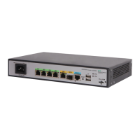
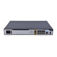
HPE FlexNetwork MSR958 User Manual

HPE FlexNetwork MSR958
4 pages
To Next Page IconTo Next Page
Page #1 background imageLoading...
Page #1 background image
The installation tools are not provided with the router. Prepare them yourself.
Installation tools
Installation accessories
Rack-mounting the router
!
!
Part number:5200-1205
HPE FlexNetwork MSR958 Routers Quick Start-6W100
Grounding
cable
Rubber feet
Cage nut
M6 screw
M4 screw
Mounting
brackets
Ruler
Wire-stripping pliers
Marker
Diagonal pliers
Flathead screwdriver Phillips screwdriver
ESD wrist strap
The router is not provided with mounting brackets. Purchase a JH317A
Mounting brackets yourself.
Applicable products
HPE MSR958 Routers (JH300A/JH301A).
!
1
2
Install cage nuts.
Attach the mounting brackets to the router.
M6
3.0±0.3 N.M

Other manuals for HPE FlexNetwork MSR958

Question and Answer IconNeed help?

Do you have a question about the HPE FlexNetwork MSR958 and is the answer not in the manual?

HPE FlexNetwork MSR958 Specifications

General IconGeneral
ModelMSR958
Connectivity TechnologyWired
Data Link ProtocolEthernet, Fast Ethernet, Gigabit Ethernet
Device TypeRouter
Product SeriesFlexNetwork
WAN Ports4 x 10/100/1000
Routing ProtocolBGP, OSPF, RIP-1, RIP-2
Remote Management ProtocolSNMP, Telnet
Encryption AlgorithmDES, MD5, SHA-1
FeaturesFirewall protection, IPv6 support, Quality of Service (QoS)
Operating SystemHP Comware
Power SupplyAC 120/230 V (50/60 Hz)
Operating Temperature0 °C to 40 °C
Storage Temperature-40°C to 70°C
Operating Humidity10% to 90% non-condensing

Summary

Rack-Mounting the Router

Install Cage Nuts

Instructions for installing cage nuts into the rack for router mounting.

Attach Mounting Brackets

Procedure for attaching the mounting brackets to the router unit.

Workbench-Mounting the Router

Attach Rubber Feet

Attach rubber feet to the router bottom and place it on the workbench.

Connecting a Fiber Port

Install Transceiver Module

Remove dust plug, insert transceiver module, and connect optical fibers.

Installing an SD Card

SD Card Installation Procedure

Remove slot cover, insert SD card, and reinstall the cover.

Connecting Grounding Cable

Grounding Procedure

Connect the ring terminal to the grounding cable for protection.

Connecting an Ethernet Cable

Supplying Power via PoE

PoE Power Connection

Connect router to device using Ethernet cable for PoE power supply.

Connecting the Power Adapter

Power Adapter Connection Steps

Connect power adapter first to router, then to power supply system.

Connecting to Configuration Terminal

Console Cable Connection

Connect router to terminal using a console cable, use adapter if needed.

Device List

Documentation

Related product manuals