Page 12 Getting Started With the Web Interface
Port Configuration and Summary
You can point to any port to display the following information about the port:
The link status (up or down).
Auto negotiation status.
Speed and full-duplex/half-duplex settings.
The maximum transmission unit (MTU), which is the largest packet size that can be transmitted on
the port.
You can left-click a port to display the Port Status page.
System LEDs
The following System LEDs reflect the status of the actual LEDs on the switch:
Power/Fault
On (green) — The switch is receiving power.
Slow blinking (green) — The switch self-test and initialization are in progress after the switch
has been powered on or reset. The switch is not operational until the LED stops blinking green.
On (orange) — If this LED is orange for a prolonged time, the switch has encountered a fatal
hardware failure.
Slow blinking (orange)—A fault or self-test failure has occurred on the switch, one of the switch
ports, or the fan. The Status LED for the component with the fault will blink simultaneously.
Off — The switch is powered off or is NOT receiving power.
Locator (Blue)
Blinking slowly—The locator function has been enabled to help physically locate the switch.
Off—The locator function is disabled and the switch is operating properly.
Port Status Indicator
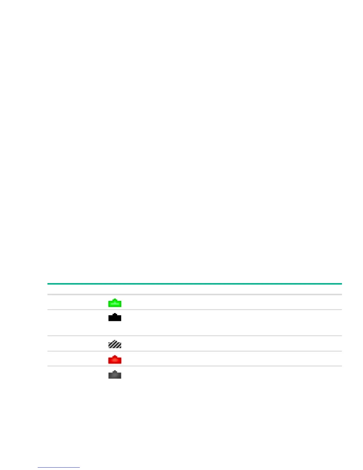
Each port in the device view is visually represented by one of five different state images.
Port State Image Description
Active
The port is connected, enabled, and the link is up.
Detached
The port is in a detached state. This state can be seen on the combo ports (SFP+).
A combo port that is associated with the RJ-45 connector may exist as an insertable
SFP+ port. When the SFP+ port is in use, the associated built-in RJ-45 connector
becomes detached.
Disabled
The port has been administrative disabled. This image is also used for “dead” ports
that may exist physically on the device but have no internal connection.
Error
The port has an error condition and may or may not be active.
Inactive
The port is connected and enabled, but the link is down (likely because no cable is
connected).

 Loading...


