8
881629-001
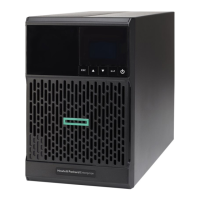
2. Presentation
2.2 Rear panels
HPE T750/T1000 G5 NA/JP
8
5
2
1
4
6a
3
6b
7
9
HPE T1500 G5 NA/JP
5
2
1
4
6a
3
6b
7
8
9
HPE T750/T1000 G5 INTL
3
2
1
4
7
6a
6b
5
8
HPE T1500 G5 INTL
2
1
4
5
6a
3
6b
8
7
(1) USB communication port
(2) RS-232 communication port
(3) Slot for optional communication card
(4) Connector for ROO (remote ON/OFF)
or RPO (remote power OFF) control
(5) Outlets for connection of critical
equipment (Primary Group)
(6a) Group 1: programmable outlets for
connection of equipment
(6b) Group 2: programmable outlets for
connection of equipment
(7) Attached 6 ft input power cord for AC
power source (5-15P)
(8) LED indicating site wiring fault (SWF)
alarm
(9) Ground screw
(1) USB communication port
(2) RS-232 communication port
(3) Slot for optional communication card
(4) Connector for ROO (remote ON/OFF)
or RPO (remote power OFF) control
(5) Outlets for connection of critical
equipment (Primary Group)
(6a) Group 1: programmable outlets for
connection of equipment
(6b) Group 2: programmable outlets for
connection of equipment
(7) Socket for connection to AC power
source
(8) Ground screw
NOTE: The Hewlett Packard Enterprise Tower G5 UPSs have three
programmable output load segments. These are defined as Group
1, Group 2, and Primary Group. The load segments/groups can be
configured via software and the unit’s user interface. For advice on
configuration through software, see the HPEPP software or the UPS
Management Card documentation. To configure the UPS through
the front panel, see "2.6 User settings". Load Groups 1 and 2 can be
programmed to switch off/on independently. The Primary Load Group
controls the outlets indicated and initiates a unit shutdown. The Primary
Load Group is intended for the most critical loads.
 Loading...