• Make sure that the AC input voltage is consistent with the rated input
voltage of the inverter.
• If the control circuit is connected to an external device with an
accessible port during power-on, an additional level of insulation
protection and isolation should be added to ensure that the original
voltage level of the external device is not changed.
• If the communication terminals of the control circuit are connected
to a PC, use an RS485/232 isolated converter that meets safety
requirements.
• Never connect control terminals other than relay terminals to AC 220V.
• The bare metal part of the power terminal wiring must be wrapped
with insulating tape.
• The control circuit and power circuit are basically insulated. Do not
touch the inverter after it is powered on.
Danger
Warning
Note:
1) Remove the shorting piece of terminals P1 and (+) when connecting a DC reactor.
2) R is the braking resistor.
3) When wiring for HD09/HD09-S, the teminal is GND, DO, AI, AO.
When wiring for HD07-S, the teminal is AO.
DI1
R1A
R1C
R1B
GND
AO/AO1
AO2
DI2
DI3
DI4
DI5
DI6
COM/GND
AI/AI1
AI2
+10
Analog input 1
GND
PE
PE
PE
RJ45
PGP
COM
A+
A-
A
B
AI3
Analog input 3
Digital input 1
DO1
CME
Digital output 1
DO
GND
Digital output
Analog output
1
Modbus
communication
Keypad or master
computer
Analog output
2
DO2
COM
Digital output 2
Digital input 2
Digital input 3
Digital input 4
Digital input 5
Digital input 6
Relay output
1
HDXX
MCCB
U
V
W
L1
P1
(+) BR
L2
L3
R
S
T
M
Power
input
Brake unit
(-)
B+
B-
Z+
Z-
PGP
COM
A-
B-
Z-
Open-collector
output encoder
R
DC
reactor
R
1)
2)
2)
3)
3) 3)
3)
3)
Analog input 2
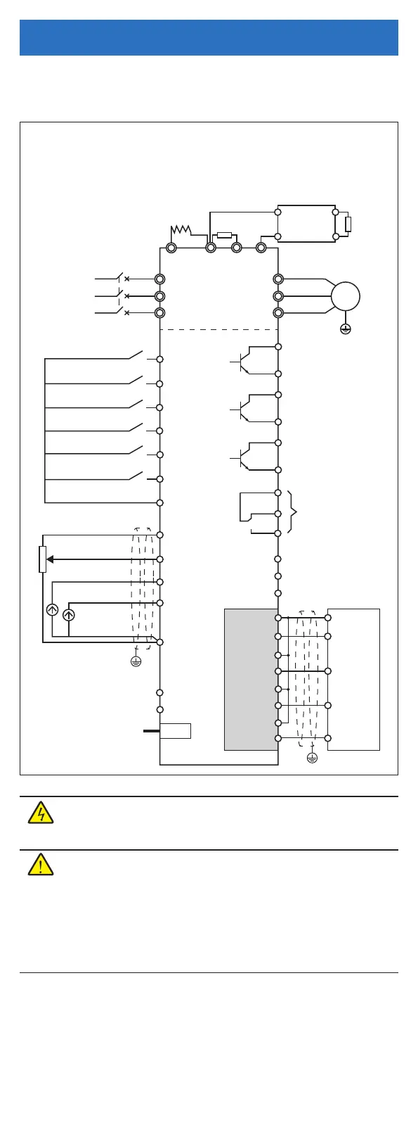
Terminal Wiring Diagram
The wiring is shown in the figure below, and the terminals of each product are
described later.
Electrical Installation

 Loading...
