Control Terminal
See control terminal layout below.
Power Terminal
See power terminal descriptions below.
(+), (-) External braking unit Only for some models
(+), BR Terminal connected to braking resistor
P1, (+) External DC reactor, shorted by default Only for some models
PE
Ground terminal, connected to
protective ground
Terminal Description Remark
L1, L2, L3 Three-phase AC power input terminal HD30/HD3N/HD50
L1, L2, L3/N Three-phase AC power input terminal
HD07-S/HD09/
HD09-S/HD20
L1, L3/N Single-phase AC power input terminal
U, V, W
Inverter output terminal connected to
three-phase AC motor
Encoder Card
HD50 products are equipped with HD-PG1-OC as standard. See terminal
descriptions below.
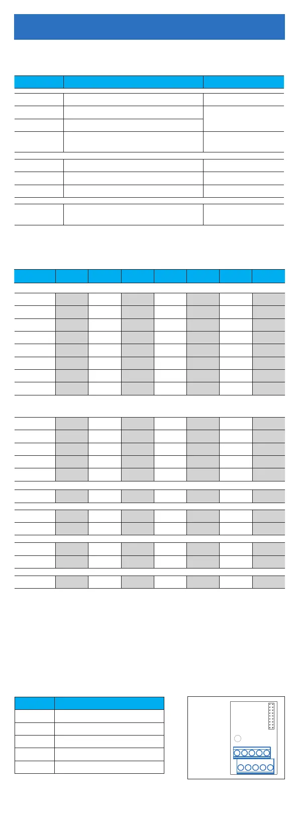
Terminal Description
PGP +12V power output
COM Power ground
A+, A- Encoder A+/A- signal
B+, B- Encoder B+/B- signal
Z+, Z- Encoder Z+/Z- signal
HD-PG1-OC
Interface HD07-S HD09 HD09-S HD20 HD30 HD3N HD50
DI1 ● ● ● ● ● ● ●
DI2 ● ● ● ● ● ● ●
DI3 ● ● ● ● ● ● ●
DI4 ● ● ● ● ● ● ●
DI5 ● ● ● ● ●
DI6 ● ● ● ●
DO/DO1
1)
● ● ● ● ● ● ●
DO2 ● ● ● ● ●
AI/AI1
1)
● ● ● ● ● ● ●
AI2 ● ● ● ● ●
AI3 ●
AO/AO1
1)
● ● ● ● ● ● ●
AO2 ● ● ● ●
RLY1 ● ● ● ● ● ● ●
+10V ● ● ● ● ● ● ●
-10V ●
RJ45 ● ● ● ● ● ●
A/B ● ●
Encoder ●
1): DO, AI, AO is for HD09/HD09-S, AO is for HD07-S, DO1, AI1, AO1 is for the rest
products.
2): The terminal can be selected as high-speed pulse input/output.
3): The terminal can be selected as input voltage/current. HD07-S is set through
F16.29, and other products are set through jumpers or DIP switches.
Electrical Installation
2)
2) 2)
2)2)
2) 2) 2)
2) 2) 2) 2)
2) 2)
3) 3) 3)
3)
3)
3)
3)
3)
3)
3)
3)
3)
3)
3)
3)
3)

 Loading...
