Chapter 7 Detailed Function Introduction Shenzhen Hpmont Technology Co., Ltd.
-36- HD09 Series User Manual V1.1
7.9 F09: V/f Controlling Parameter
Ref. Code Function Description Setting Range [Default]
F09.01 Motor V/f frequency values F3 F09.03 - 100.0 (F08.03) [100.0%]
Motor V/f voltage values V3
F09.04 - 100.0 (F08.01) [100.0%]
F09.03 Motor V/f frequency values F2 F09.05 - F09.01 (F08.03) [0.0%]
Motor V/f voltage values V2
F09.06 - F09.02 (F08.01) [0.0%]
F09.05 Motor V/f frequency values F1 0.0 - F09.03 (F08.03) [0.0%]
Motor V/f voltage values V1
0.0 - F09.04 (F08.01) [0.0%]
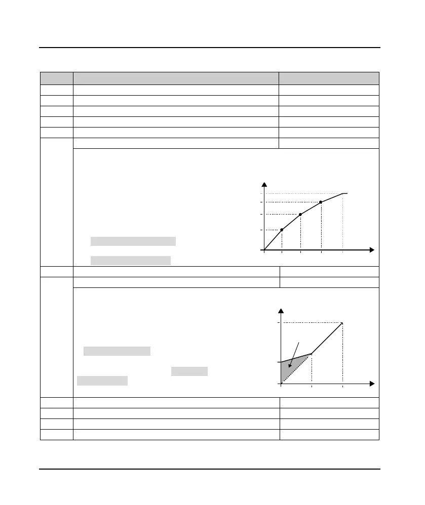
F09.01 - F09.06 is customized V/f curve.
• Using V1 / f1, V2 / f2, V3 / f3 three-point line way to define V/f curve, in order to apply to special load
characteristic.
• According to the actual working condition,
setting up reasonable curve, in order to conform
to the characteristics of the load to the greatest
extent.
• F09.01, F09.03, F09.05 is percentage compared
to motor rated frequency (F08.03).
• F09.02, F09.04, F09.06 is percentage compared
to motor rated fvoltage (F08.01).
F09.08 Cut-off points of motor torque increase manually 0.0 - 50.0 (F08.03) [30.0%]
To compensate for the low frequency torque characteristics, we can make some improvement on output
voltage compensation.
F09.07 is manual torque way to ascend.
• In 0, means automatic torque said.
Should be in accordance with the motor
nameplate parameters and set up correctly
rated frequency (F08.03).
F09.08 is percentage cpmpared to motor rated
frequency (F08.03).
• F09.08 max. = F08.03 × 50%.
Motor slip compensation gain
Motor slip compensation filtering time
F09.11 Motor slip compensation limit 0.0 - 250.0 [200.0%]
Motor to compensate normal time
F08.03
F08.01
0
F09.02
F09.04
F09.06
F09.05 F09.03 F09.01
Voltage
Frequency
V1,F1
V2,F2
V3,F3
Voltage
0
Frequency
F08.03
F08.01
F09.08max
Voltage of manual
to
rque boost
Boost
ed
value
 Loading...
