Chapter 7 Detailed Function Introduction Shenzhen Hpmont Technology Co., Ltd.
-44- HD09 Series User Manual V1.1
7.11 F16: Analogue Input / Output Terminal Parameter
Ref. Code Function Description Setting Range [Default]
F16.00 Keypad potentiometer function selection 0 - 5 [0]
0: Resevered.
2: Frequency setting.
3: Auxiliary frequency setting.
5: PID feedback process.
F16.06 AI gain 0.00 - 10.00 [1.00]
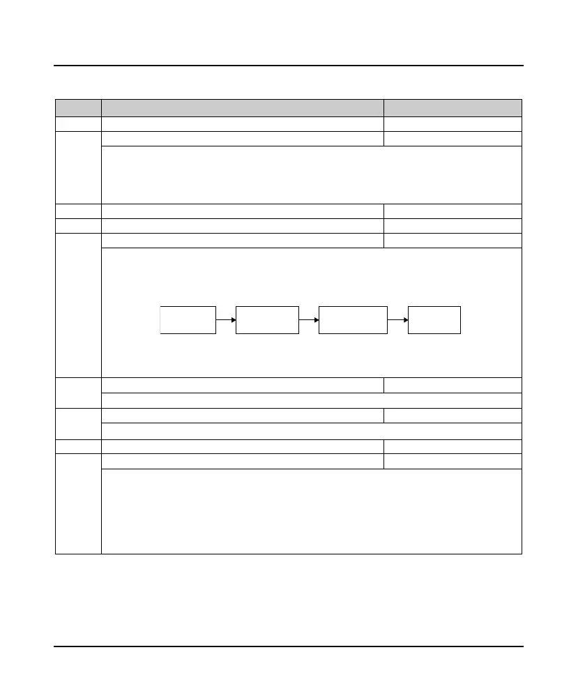
AI input is selected as open-loop frequency setting channel, the analog input needs to be filtered, offset, gain
calculation processed, only to get the actual analog, as shown below.
• The relationship between the AI input and the set frequency is set by F05.01 - F05.04.
• Calculation formula: Calculated value = F16.06 × AI Actual input + F16.05.
F16.07 defines the filter time of the channel and filters the input signal.
• The longer the filtering time, the stronger the anti-interference ability, but the slower the response. The
shorter the filtering time is, the faster the response time becomes.
F16.17 DI4 the largest terminal input pulse frequency 0.0 - 50.0 [10.0kHz]
Define DI4 terminals as the maximum input pulse frequency when the input pulse.
F16.18 DI4 terminal input pulse filtering time 0 - 500 [10ms]
To filter the DI4 terminals of the input pulse frequency, to filter out pulse frequency of small fluctuations.
F16.19 AO function selection 0 - 12 [2]
0: Reserved.
2: Preset frequency (0 - maximum output frequency).
3: Motor rpm (0 - the maximum output frequency corresponds to the speed).
5: Output current (0 -2 times the motor rated current).
11: Output voltage (0 - 1.2 times the inverter rated voltage).
12: DC bus voltage (0 - 2.2 times the inverter rated voltage).
AI actual
input
Filter F16.07
Value after
caculating
Gain F16.06
offset F16.05
 Loading...
