Shenzhen Hpmont Technology Co., Ltd. Chapter 7 Detailed Function Introduction
HD09 Series User Manual V1.1 -45-
Ref. Code Function Description Setting Range [Default]
F16.22 AO polarization -100.0 - 100.0 [0.0%]
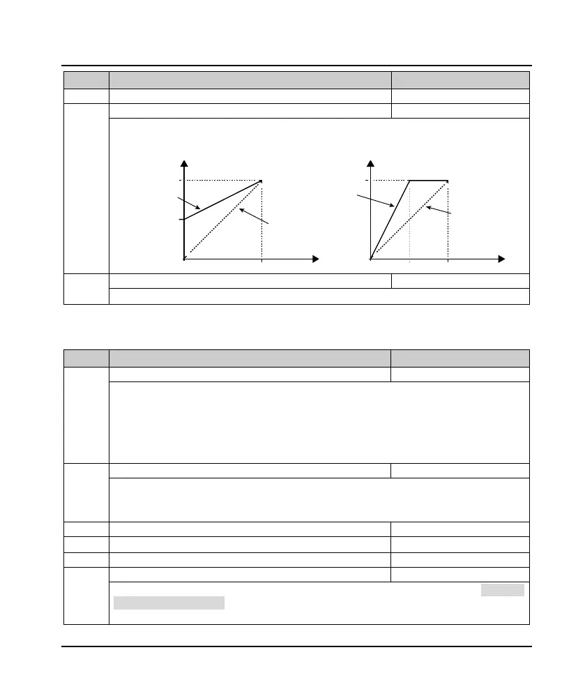
If the user needs to adjust the AO output proportional relationship, can be achieved through the output gain,
as shown below.
• Calculation formula: AO actual output = F16.23 × Calculated value + F16.22.
DO terminal output maximum pulse frequency
Defines the DO terminal for the largest output pulse frequency pulse output.
7.12 F17: SCI Communication Parameter
Ref. Code Function Description Setting Range [Default]
0: 1-8-2 format, no parity, RTU. 1-8-2 format indicates that the communication format is 1 bit start bit, 8 bits
data bit, 2 bit stop bit.
1: 1-8-1 format, even parity, RTU. 1-8-1 format indicates that the communication format is: 1 bit start bit, 8
bits data bit, 1 bit stop bit.
2: 1-8-1 format, odd parity, RTU. 1-8-1 format indicates that the communication format is: 1 bit start bit, 8 bits
data bit, 1 bit stop bit.
0: 1200bps.
1: 2400bps.
2: 4800bps.
3: 9600bps.
4: 19200bps.
5: 38400bps.
When set to 0, it is represented as a broadcast address.
This machine response time
F17.04 LAN communication timeout detection time 0.0 - 1000.0 [0.0s]
When the time interval between the two returns to the local data continues to exceed F17.04, the E0028 fault
(SCI communication timeout) is reported and the inverter continues to run.
• F17.04 = 0, the drive does not detect the communication timeout.
AO actual output
100%
F16.23=100%
F16.22=0
F16.22=0
F16.23=200%
AO actual output
F16.22=0
F16.23=100%
F16.22=50%
F16.23=50%
50%
100%
0V 10V 0V 5V 10V
Value before
calculating
Value before
calculating
 Loading...
