Shenzhen Hpmont Technology Co., Ltd. Chapter 7 Detailed Function Introduction
HD09 Series User Manual V1.1 -41-
Ref. Code Function Description Setting Range [Default]
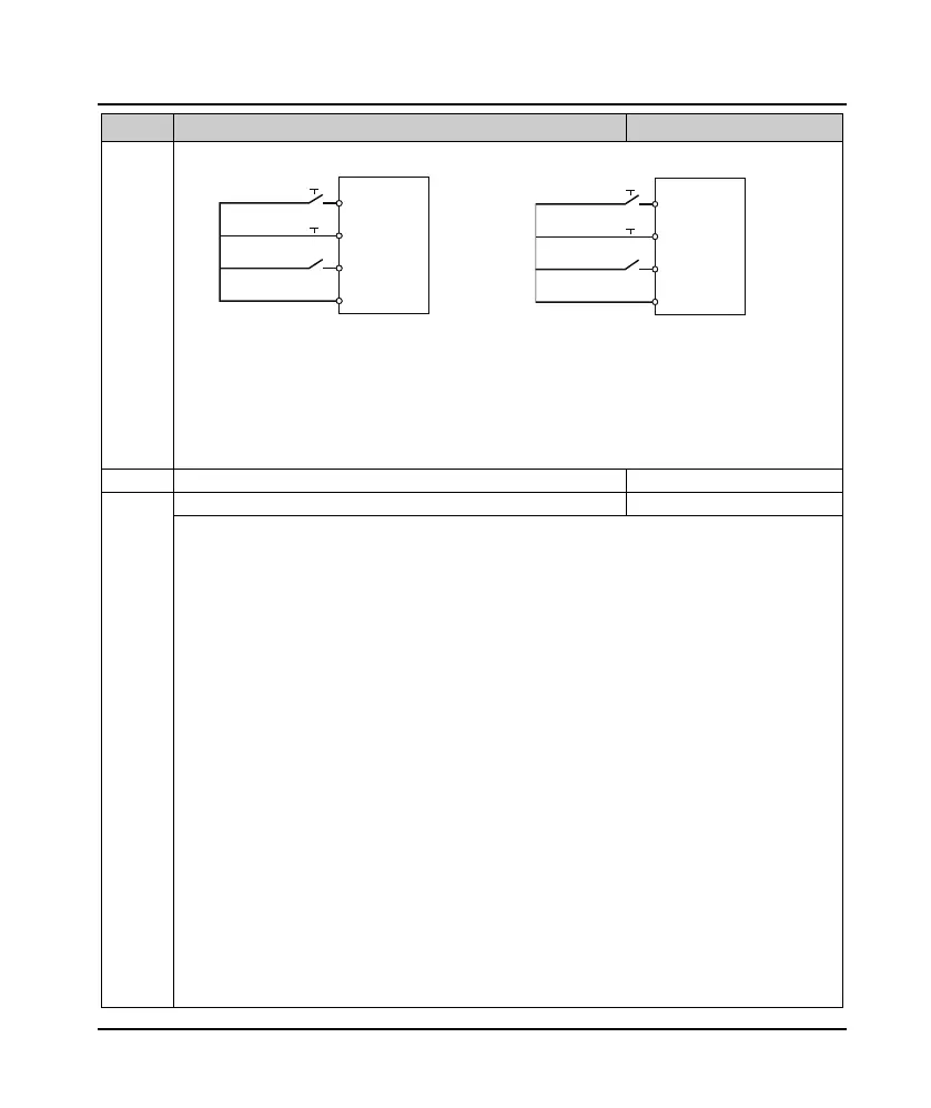
F15.16 = 2 F15.16 = 3
• SB1: Normally closed stopping button (falling
edge effective)
• SB2: Normally open forward button (rising edge
effective)
• SB3: Normally open reverse button (rising edge
effective)
• K: Direction selection terminals (PMCSx)
• K = 0 (Forward); K = 1 (Reverse)
• SB1: Normally closed stopping button (falling
edge effective)
• SB2: Normally open running button (rising edge
effective)
0: Reserved.
• So that the output terminal in a non-functional state, nor make any action.
2: The inverter is running.
• When the inverter is running, the indicator output.
3: The inverter is running forward.
• When the inverter is running forward, the output signal output.
4: The inverter is running reversely.
• When the inverter is running in reverse, the output signal output.
5: DC brake.
• When the inverter is in DC braking, the output signal output.
9: Frequency level detection signal (FDT).
• See, for example, F15.31, F15.32.
11: Frequency arrival (FAR).
• See F15.27 for details.
20: Data output by SCI communication.
• There is a SCI communication that directly controls the DO or relay output indication signal.
21: Set run time arrive.
• See F15.36 for details.
23: Set the count value arrive.
• See F15.37, F15.38 for details.
24: Specifies the count value arrive.
• See F15.37, F15.38 for details.
FWD
Three-wire
R
EV
SB2
SB1
SB3
DIx
DIz
DIy
GND
HD09
F
WD
T
hre
e-wir
e
FW
D
/ R
EV
SB2
SB1
K
DIx
DIz
DIy
GND
HD09
 Loading...
