Gx Series
EN - 43
6.4.3 STD Mode – Generic test
This mode performs the impedance measurement and the calculation of prospective short
circuit current without applying any evaluation. Therefore, at the end of the test, no outcome
is given by the instrument.
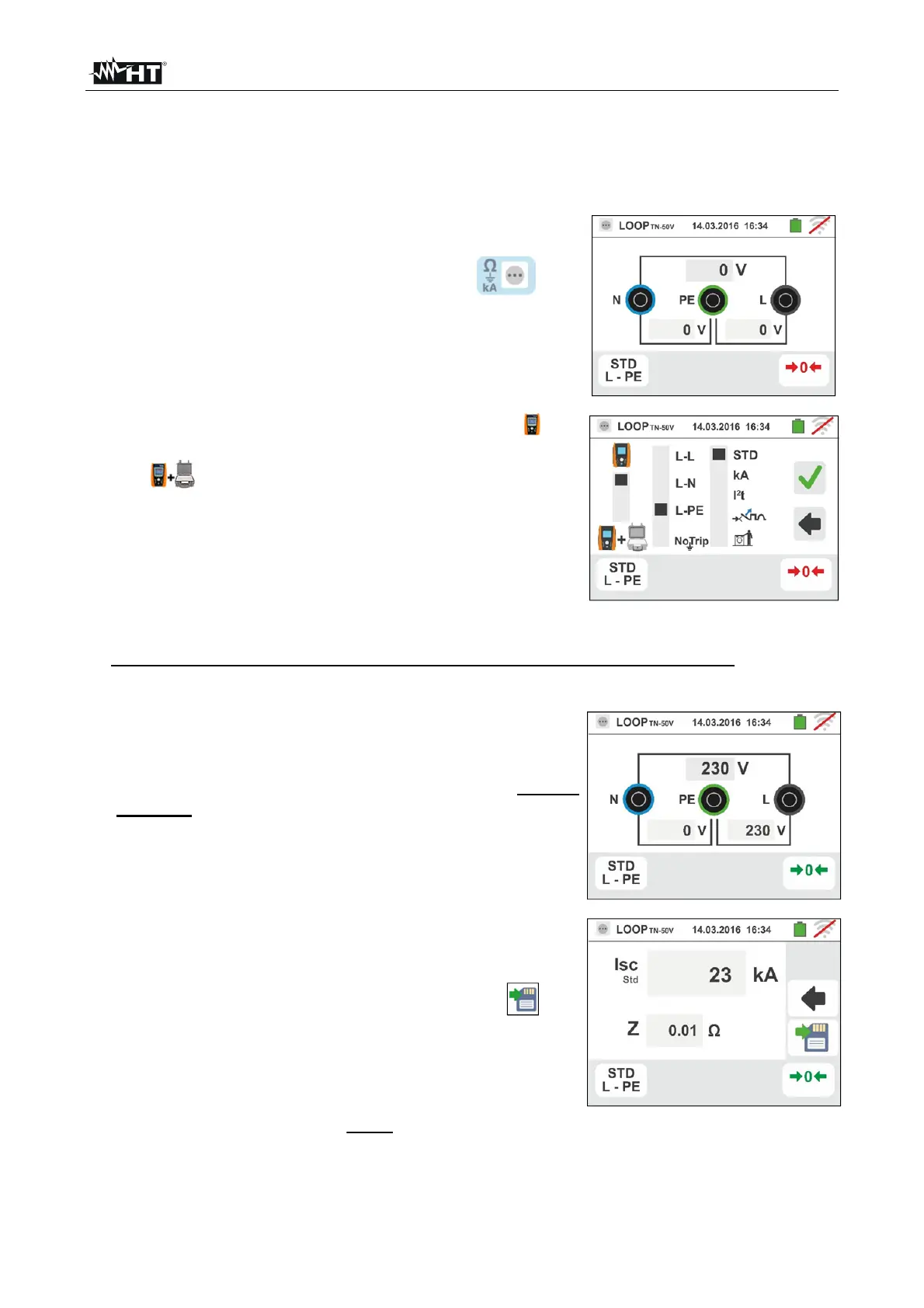
1. Select the options “TN, TT or “IT”, “25 or 50V”, “50Hz or
60Hz” and the reference voltage in the general settings
of the instrument (see § 5.1.4). Touch the icon.
The screen to the side appears on the display.
Touch the lower icon. The following screen appears on
the display:
2.
Move the left slide bar reference by selecting the icon
to execute the measurement only with the instrument or
the icon to execute the measurement with the
instrument + optional accessory IMP57 (see § 6.4.13).
Move the central slide bar reference by selecting the "
L-L, L-N or L-PE” options. Move the right slide bar
reference by selecting the "STD" option. Confirm the
choice by going back to the previous screen.
3. If possible, disconnect all loads connected downstream of the measuring point, as the
impedance of these users could distort the test results.
4. Perform the preliminary calibration of the test leads as described in § 6.4.2. Connect the
shuko plug, the alligator clips or the remote lead to the electrical mains according to Fig.
18, Fig. 19, Fig. 20 and Fig. 22.
5. Note the presence of the correct voltage values
between L-N and L-PE corresponding to the selections
carried out in the initial phase (see § 5.1.4) as shown in
the screen to the side. Press the GO/STOP key for few
seconds or the START key on the remote lead. During
this whole stage, do not disconnect the measuring leads
of the instrument from the system under test. The
following screen appears on the instrument's display:
6. The value of the assumed short-circuit current (Isc) is
shown in the upper part of the display, while the
Line/Loop Z
PE
impedance is shown at the bottom of the
display. Press the SAVE button or touch the icon
to save the measurement (see § 7.1).
The Standard (Std) assumed short-circuit current (Isc)
is calculated using the following formula:
MEAS
NOM
SC
Z
U
I
Z
MEAS
= measured L-L,L-N,L-PE loop impedance
U
NOM
= nominal voltage (depend on the system)
 Loading...