Gx Series
EN - 94
4. Insert the green, blue and black connectors of the three-pin shuko plug into the relevant
instrument input terminals B3, B4, B1. As an alternative, use the single cables and apply
the relevant alligator clips to the free ends of the cables. It is also possible to use the
remote lead by inserting its multipolar connector into the input lead B1. Connect the
shuko plug, the alligator clips or the remote lead to the electrical mains according to Fig.
12, Fig. 13, Fig. 14, Fig. 15 and Fig. 16
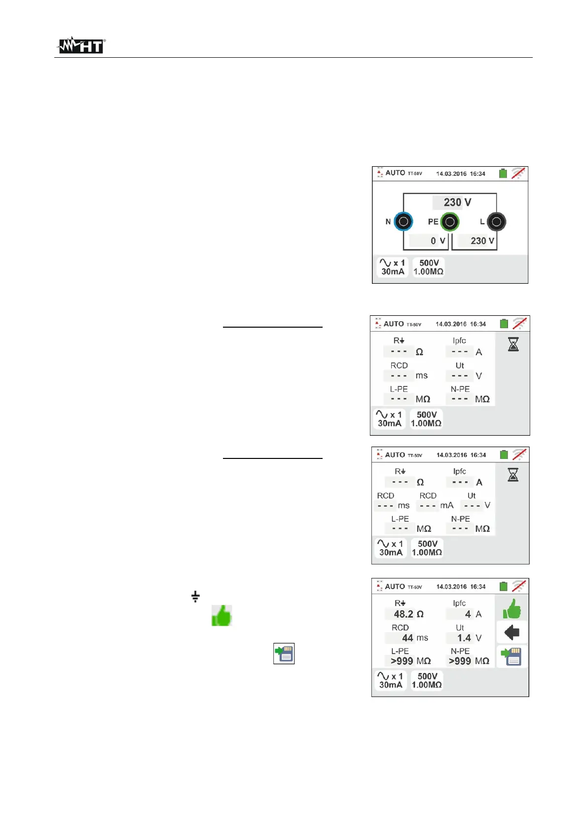
5. Note the correct voltage values between L-N and L-PE
as shown in the screen to the side
AutoTest in TT systems
6.10.1.
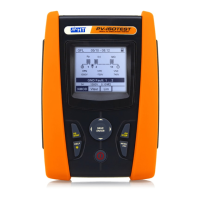
6. Press the GO/STOP key for few seconds or the
START key on the remote lead. During this whole
stage, do not disconnect the measuring leads of the
instrument from the system under test. In case of RCD
tripping time measurement selection the screen to
the side appears on the display when the hourglass
icon indicates the performance of the test
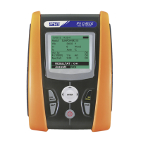
7. Press the GO/STOP key for few seconds or the
START key on the remote lead. During this whole
stage, do not disconnect the measuring leads of the
instrument from the system under test. In case of RCD
tripping current measurement selection the screen to
the side appears on the display when the hourglass
icon indicates the performance of the test
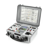
8. In case of positive result of the three test sequentially
performed as NoTrip (see § 13.8), RCDX1 (see §
13.4) and M L/N-PE the symbol is shown and the
screen to the side is displayed by the instrument
Press the SAVE button or touch the icon to save
the measurement (see § 7.1)


 To Next Page