JUPITER
IT - 9
4.2.6. LoZ function
This mode allows carrying out AC/DC voltage measurement with a low input impedance, in
order to eliminate wrong readings due to parasite voltages for capacitive couplings.
CAUTION
By plugging the instrument between the phase and earth conductor,
because of the low impedance of the instrument during measurement, RCD
protections may trip while carrying out the test. If this test is to be carried
out, first carry out a measurement of at least 5s between phase and neutral
in the presence of voltage.
4.2.7. AC+DC function
The instrument is capable of measuring a possible presence of overlapping alternating
components on a generic direct waveform (voltage or current). This can be useful when
measuring typical impulsive signals of non-linear loads (e.g. welding machines, ovens).
4.2.8. Inrush current function (INRUSH)
Measurement of inrush current (see § 5.9) is intended as the recognition of an event
detected upon exceeding of a trigger threshold. If the instant value exceeds this threshold
(fixed, equal to 1%FS clamp), the instrument shows on the display the maximum Peak
value (calculated in 1ms) and the maximum RMS value calculated with a time which can
be selected among options: 16.7ms, 20ms, 50ms, 100ms (default), 150ms, 175ms and
200ms.
4.2.9. Disabling the Auto Power Off function
In order to preserve internal batteries, the instrument switches off automatically
approximately 15 minutes after it was last used. Press key MODE/MXMNPK or move
selector from OFF position to switch on the instrument. To disable the Auto Power Off
function, proceed as follows:
Switch off the instrument (OFF)
Press and hold key to switch on the instrument. The symbol “ ” disappears from
the display
Switch off and then on again the instrument or press key MODE/MXMNPK to enable
the function again.
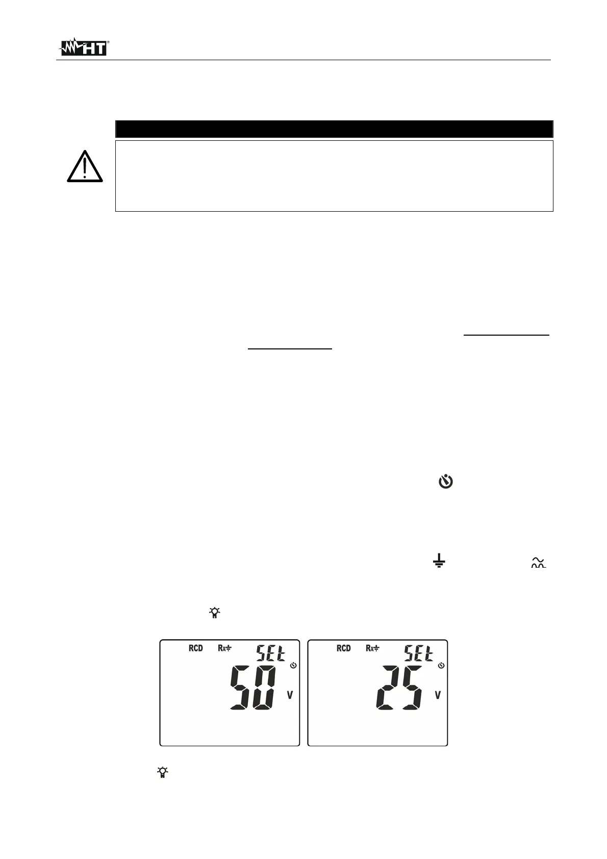
4.2.10. Setting the contact voltage limit
In order to set the limit on contact voltage Ut, used in positions Ra
Loop and RCD ,
proceed as follows:
1. Switch off the instrument (OFF)
2. Press and hold key / switch on the instrument by turning the rotary switch. The
screen in Fig. 5 – left side appears on the display with a flashing “Set” symbol.
Fig. 5: Setting the contact voltage limit
3. Press keys / or to select limit values 50V or 25V.
4. Press key GO/HOLD to confirm and go back to measuring screen.