JUPITER
IT - 16
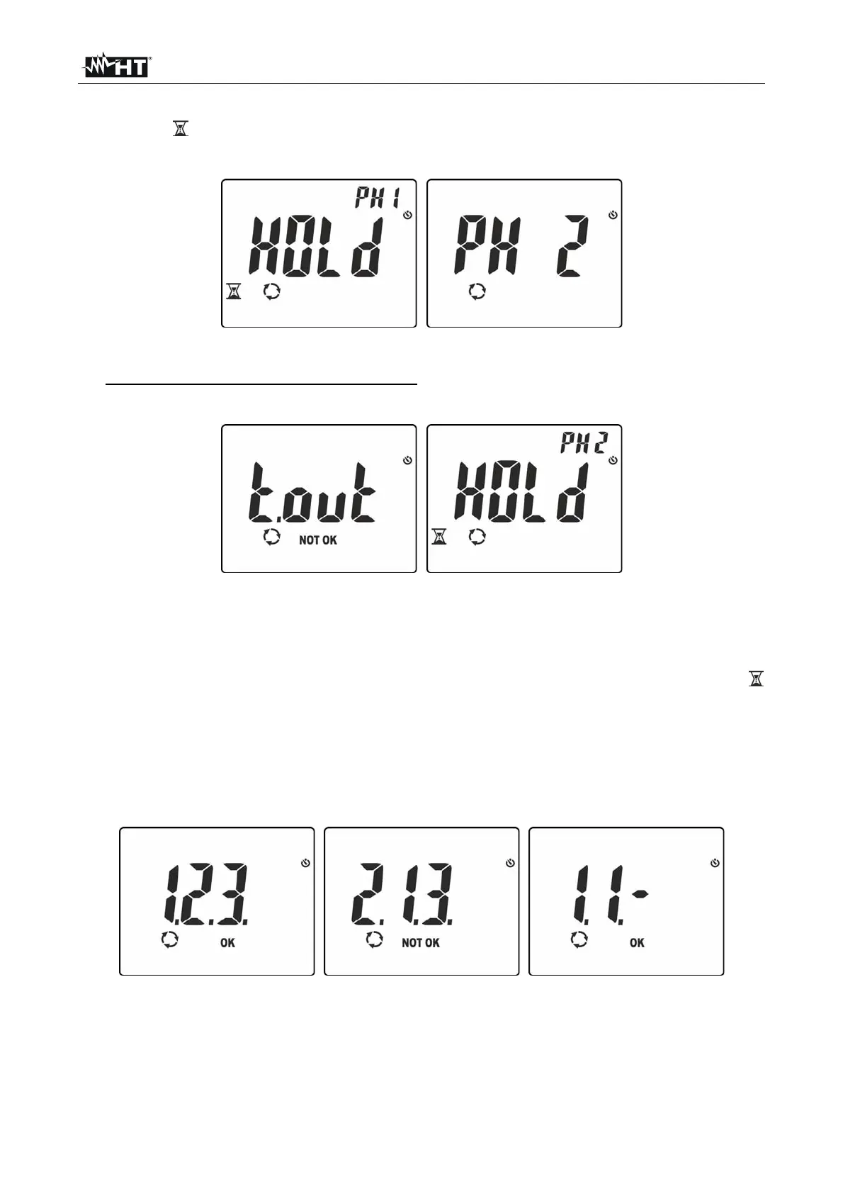
4. In conditions of correct voltage and frequency, the instrument shows message “HOLD”,
symbols and “PH1” and the buzzer sounds continuously, waiting for a stable voltage
value on phase L1 to be detected (see Fig. 14 – left side).
Fig. 14: Detecting phase L1 and waiting for phase L2
5. Do not remove the lead from phase L1 until message “PH 2” appears flashing on the
display (see Fig. 14 – right side)
Fig. 15: Detecting phase L1 and waiting for phase L2
6. Position the red lead onto phase L2 of the three-phase system to be tested (see Fig.
12). In case passage between phase L1 and phase L2 takes more than 10s, the
instrument shows message “t.out” on the display (see Fig. 15 – left side). In conditions
of correct voltage and frequency, the instrument shows message “HOLD”, symbols
and
“PH2” and the buzzer sounds continuously, waiting for a stable voltage value on
phase L2 to be detected (see Fig. 15
– right side)
7. Upon detection of a stable voltage value on phase L2, the instrument automatically
shows message “1.2.3.” (test OK) or message “2.1.3” (test NOT OK) as shown in Fig.
16.
Fig. 16: Results of phase sequence and phase concordance test
8. In case it is necessary to check phase concordance between two parallel three-phase
systems, after detection of phase L1 of the first system, position the lead on phase L1
of the second system. The correct final result is message “1.1-” (see Fig. 16 – right side)