Connecting the Lync 12 to Two Multi-Channel Ampliers
12
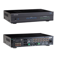
How to Connect
Use the Variable Line Outputs on the Lync to connect to the Line Inputs on the ampliers for each zone. We
include twelve 3’ shielded stereo patch cables with the Lync 12 for this purpose.
A mono 3.5mm patch cable (included) should be connected from the Trigger Out on the Lync 12 to the Trigger
In on the rst multi-channel amplier. A mono 2.5mm to 3.5mm patch cable (included) should be connected from
the 12V Control Out on the rst amplier to the Trigger In on the second amplier. The “trigger” is only active
when a zone is powered on which means the multi-channel ampliers are only active when a zone is on. When
all zones are off, the multi-channel ampliers will automatically return to sleep mode.
**Always power off the Lync 12 Controller and multi-channel ampliers before connecting
or disconnecting any 12V Trigger cable.**
Power
123456789
10 11 12 13 14 15 16 17 18
123456
789101112
Zone Status Source Signal Strength
AC 120V~60Hz
FUSE T2AL/250V
Power Consumption: 180W
ROUTED IR OUT
SOURCE INPUT
KEYPAD PORTS
IR IN
13
SOURCE 13
14
15
16
17
SOURCE 18
MP3
L
ZONE 1 PREOUT ZONE 2 PREOUT ZONE 3 PREOUT ZONE 4 PREOUT ZONE 5 PREOUT ZONE 6 PREOUT
MONO STEREO MONO STEREO MONO STEREO MONO STEREO MONO STEREOMONOSTEREO
R
LRLR
LRLR
LR LR LR LR
LRLRLR
R
L
2
1
4
3
6
5
8
7
10
9
12
11
IR IN
RS232
INTERFACE
GLOBAL
IR OUT
12V/DC
TRIGGER
100mA
IN OUT
System
TRIGGER
AC/DC 3-20V
Mute
Made in Ta iwan
CAUTION
To Prevent Electric Shock,
Do Not Remove Cover. No
User-Serviceable Parts Inside,
Refer Servicing To Qualified
Service Personnel.
WARNING
To Prevent Fire Or Shock
Hazard, Do Not Expose This
Unit To Rain Or Moisture.
FIXEDVA RIABLE
OUTPUT TO AMP
L
ZONE 7 PREOUT ZONE 8 PREOUT ZONE 9 PREOUT ZONE 10 PREOUT ZONE 11 PREOUT ZONE 12 PREOUT
MONO STEREO MONO STEREO MONO STEREO MONO STEREO MONO STEREOMONOSTEREO
R
LRLR
LRLR
LR LR LR LR
LRLRLR
FIXEDVA RIABLE
OUTPUT TO AMP
IR IN
DOOR INTERFACE
2.5mm to 3.5mm
trigger cable
3’ Shielded Stereo
Patch Cables
Speaker Connections
Left
Left Left Left
Left Left
Right
Right Right
Right
Right Right
Left Right
Out 2
Out 1
In 2
In 1
1
2
3
Line In
4
5
6
7
8
9
10
11
12
Line In
1 2 Line
Bridged
L L+R RL L+R RL L+R RL L+R RL L+R RL L+R RL L+R RL L+R RL L+R RL L+R RL L+R RL L+R R
On
Auto On
3-30V
AC/DC
Trigger In
AC 120V-60Hz
Fuse: T15A/250V
Power Consumption: 1200W
12V DC
Control
Out
Trigger
1 2 Line1 2 Line 1 2 Line 1 2 Line 1 2 Line 1 2 Line 1 2 Line 1 2 Line 1 2 Line 1 2 Line1 2 Line
Line In Line In Line In Line In
Bridged Bridged Bridged Bridged Bridged
DMA-1240
Power
Vol 1 Vol 2 Vol 3 Vol 4 Vol 5 Vol 6 Vol 7 Vol 8 Vol 9 Vol 10 Vol 11 Vol 12
3’ Shielded Stereo
Patch Cables
Speaker Connections
Left Right
Out 2
Out 1
In 2
In 1
1
2
3
Line In
4
5
6
7
8
9
10
11
12
Line In
1 2 Line
Bridged
L L+R RL L+R RL L+R RL L+R RL L+R RL L+R RL L+R RL L+R RL L+R RL L+R RL L+R RL L+R R
On
Auto On
3-30V
AC/DC
Trigger In
AC 120V-60Hz
Fuse: T15A/250V
Power Consumption: 1200W
12V DC
Control
Out
Trigger
1 2 Line1 2 Line 1 2 Line 1 2 Line 1 2 Line 1 2 Line 1 2 Line 1 2 Line 1 2 Line 1 2 Line1 2 Line
Line In Line In Line In Line In
Bridged Bridged Bridged Bridged Bridged
DMA-1240
Power
Vol 1 Vol 2 Vol 3 Vol 4 Vol 5 Vol 6 Vol 7 Vol 8 Vol 9 Vol 10 Vol 11 Vol 12
Left
Left Left Left
Left Left
Right
Right Right
Right
Right Right