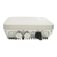
Item Category Silk Screen Description
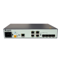
Service electrical
interfaces
FE/GE2 and FE/GE3
(ATN 905A)
Receive FE/GE services using the 4.4.2
Ethernet Cables.
FE/GE1 to FE/GE3 (ATN
905A-P)
Receive FE/GE services using the 4.4.2
Ethernet Cables and support power over
Ethernet (PoE).
Button Reset button RST When you press and then release this button,
the board is reset.
Indicators Device status indicator ALM Indicates alarms.
STAT Indicates the working status.
PWR Indicates the power status.
Electrical interface
status indicator
- One LINK indicator and one ACT indicator
are present above each RJ-45 electrical
interface. They are used to indicate the port
connection status and data receiving and
transmission status.
SFP interface status
indicators
L/A2 to L/A5 Indicates the port connection status or
data receiving and transmission status.
NOTE
l ATN 905A
l FE/GE2 and FE/GE3 are Combo interfaces and either of them includes one SFP interface and one electrical interface. The
SFP and electrical interfaces cannot be used at the same time.
l FE/GE electrical interfaces do not support PoE.
l ATN 905A-P
l FE/GE1 is a Combo interface that includes one SFP interface and one electrical interface. The SFP and electrical interfaces
cannot be used at the same time.
l FE/GE electrical interfaces support PoE. FE/GE3 supports a maximum output power of 130 W power (non-standard PoE,
mainly used for Huawei small base station devices) while FE/GE1 and FE/GE2 shares 60 W power consumption.
ATN 905 Multi-service Access Equipment
Product Description 4 Hardware Structure
Issue 01 (2013-05-30) Huawei Proprietary and Confidential
Copyright © Huawei Technologies Co., Ltd.
38
 Loading...