Do you have a question about the Huawei Backup Box-B1 and is the answer not in the manual?
Describes the Backup Box's role in controlling grid-tied/off-grid states in PV systems.
Covers essential requirements for installing the Backup Box, including environmental and safety precautions.
Lists crucial safety precautions and preparatory steps before making electrical connections.
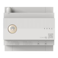
The Backup Box (B0, B1) is an essential component in residential rooftop PV plant systems, designed to manage the inverter's grid-tied and off-grid states. Its primary function is to ensure continuous power supply to off-grid loads during grid failures, switching the inverter to an off-grid backup mode. When the grid recovers, the Backup Box seamlessly switches the inverter back to the grid-tied state, restoring normal operation. This functionality is crucial for maintaining household power during outages, providing reliability and energy independence.
The core function of the Backup Box is to provide an automatic switching mechanism between grid-tied and off-grid operation for a PV inverter system. In a typical setup, the system includes PV strings, an energy storage system (ESS), an inverter, the Backup Box, a management system, an AC switch, and a power distribution unit. When the main power grid is operational, the inverter operates in a grid-tied state, feeding excess solar energy back into the grid or charging the ESS. However, upon detection of a grid failure, the Backup Box intervenes, isolating the inverter from the grid and enabling it to supply power to designated off-grid loads from the PV array and/or the ESS. This ensures that critical household appliances remain powered even when the public grid is down. Once the grid power is restored, the Backup Box facilitates the smooth transition back to grid-tied operation.
The Backup Box supports various grid types, including TN-S, TN-C-S, and TT, ensuring compatibility with a wide range of electrical infrastructures. However, it's important to note that for three-phase, three-wire inverter configurations, the Backup Box does not support off-grid operation. This limitation should be considered during system design and installation.
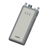
The device features several key ports and components:
Installation of the Backup Box requires careful attention to environmental conditions and electrical connections. When installed outdoors, it is recommended to place the device in a sheltered location or install an awning to protect it from direct sunlight, which can affect its performance and lifespan. A surge protective device (SPD) is also necessary on the grid side of the Backup Box to protect against voltage spikes.
The installation process involves mounting the device securely to a wall, ensuring adequate clearance for ventilation and maintenance. The mounting holes and dimensions are provided to guide installers in preparing the installation site. When drilling holes, it is crucial to avoid damaging water pipes or power cables embedded in the wall. The device comes with M6x60 expansion bolts, suitable for solid concrete walls. For other wall types, appropriate bolts must be sourced, ensuring the wall can support the device's weight. In residential areas, it is advised not to install the Backup Box on drywalls or similar materials with poor sound insulation, as the inverter's operational noise might be noticeable.
Electrical connections are a critical aspect of the Backup Box's usage. Cables must be connected in accordance with local installation laws and regulations. Before making any connections, all circuit breakers on the Backup Box and connected switches must be in the OFF position to prevent electric shocks from high voltage. The required cable types and cross-sectional areas are specified for PE, off-grid load output, grid AC output, inverter AC input, and signal cables. A crucial safety instruction is to never connect the neutral wire to the enclosure as a PE cable, as this can lead to electric shocks.
Connecting the power cables involves stripping the insulation, crimping terminals, and securing them to the designated ports (X1 for off-grid load, X2 for grid AC output, X3 for inverter AC input) with specified torque values. The sequence of connecting cables to a single-phase Backup Box (L, N, PE from left to right) and a three-phase Backup Box (L1, L2, L3) must be strictly followed to ensure proper device operation.
The installation of a short-circuiting plate is another important step. This plate ensures that the neutral wire is not suspended in off-grid mode, which is particularly relevant in regions like Australia where the neutral wire cannot be disconnected from the power grid. For other regions, such as Germany, where the neutral wire needs to be disconnected in off-grid mode, the short-circuiting plate is inserted between different terminals. Incorrect installation of this plate can lead to short circuits or improper off-grid functionality.
Signal cables are connected to the COM port (X4) of the Backup Box and the inverter's COM port. These cables facilitate communication between the Backup Box and the inverter, allowing the Backup Box to send feedback signals to the inverter. The pin definitions for the COM ports on various inverter models (e.g., SUN2000-(2KTL-6KTL)-L1, SUN2000-(3KTL-12KTL)-M1) are provided to ensure correct wiring.
After installation, a verification process is necessary to confirm that all connections are correct and secure, cables are routed properly, and the installation environment is clean and tidy. Powering on the system involves a sequence of steps: checking AC voltage in the power distribution box (PDB), turning on the PDB AC switch (with the Backup Box load switch OFF), verifying grid AC terminal connections, and then turning on the DC switches for PV strings and the inverter. Finally, the AC switch of the Backup Box is turned on, and the LED indicators on the inverter are observed to confirm the running status.
System commissioning involves configuring parameters through the FusionSolar app. This includes enabling "Off-grid mode," setting the "Backup power SOC" (State of Charge), and choosing between "Automatic switching" or "Manual switching" for grid-tied/off-grid mode. The "Backup power SOC" determines the battery's discharge limit in grid-tied mode and ensures power supply to off-grid loads until the battery reaches its end-of-discharge capacity during grid failures. The switching mode defines how the system transitions between grid-tied and off-grid states.
Verifying the off-grid/grid-tied switching function involves powering on the Backup Box, enabling off-grid mode via the app, then simulating a grid failure by turning off the AC switch in the PDB. The inverter indicators should show a steady orange, confirming off-grid operation. Restoring grid power by turning on the AC switch should cause the indicators to blink green slowly until the inverter reconnects to the grid.
Routine maintenance is crucial for the long-term and proper operation of the Backup Box. It is recommended to perform periodic checks to ensure system reliability.
Troubleshooting guidance is provided to address common issues. If the Backup Box is suspected to be damaged, a multimeter can be used to check the connectivity between its terminals, with specific conduction statuses provided for single-phase and three-phase models. Inconsistent conduction status indicates damage. Other troubleshooting steps include contacting customer service if the inverter remains in off-grid state after grid recovery, understanding alarm behavior when off-grid mode is enabled without a connected Backup Box, and disabling off-grid mode if the Backup Box is not used after initial setup to prevent operational issues. For single-phase Backup Boxes, abnormal noises during switching may indicate a reverse connection of the inverter AC terminal to the power grid AC terminal, requiring a check and correction.
| Brand | Huawei |
|---|---|
| Model | Backup Box-B1 |
| Category | Controller |
| Language | English |