26
4815
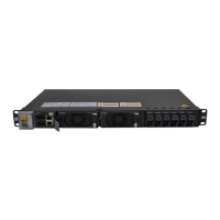
Only two countersunk
screws are required.
Installing the BBU Cables
j
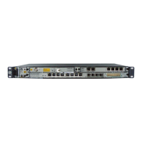
Installing the BBU in the RRU3004 Rack
220 V input power
GEHUB or HUBBTSE1/T1 port of the BBUE1/T1 cable
Power supply equipment of the customerAC INPUT port of the 4815Input power cable for the 4815
Ground terminal of the RRU3004 rackBolts for the mounting ears of the 4815PGND cable for the 4815
The Other End Is Connected to...One End Is Connected to...Cable
External ground busbarGround bar of the standExternal PGND cable
Ground terminal of the RRU3004 rackGround terminal of the RRU3004 rackEquipotential cable for the rack
LOAD1 port of the 4815PWR port of the BBUPower cable for the BBU
RS232/RS485 port of the 4815, close to the
232 side
MON1 port of the BBU4815 - BBU monitoring signal cable
Ground bar of the standGround terminal of the RRU3004 rackPGND cable for the RRU3004 rack
The end with the optical cable labels 1A and
1B is connected to the CPRI_W port of the
cabling cavity of the RRU.
The end with the optical cable labels 2A and
2B is connected to CPRI ports 0 to 5 of the
GTMU of the BBU.
CPRI optical cable
The mounting ears need to be installed in an
inverse manner during the installation of the
4815.

 Loading...


