LampSite Solution
Product Description
5 Technical Specifications
Huawei Proprietary and Confidential
Copyright © Huawei Technologies Co., Ltd.
Receiver
Sensitivity
with One
Antenna
(dBm)
Maximum Output Power
(mW)
1 carrier. The
bandwidth per
carrier is 5, 10, 15,
or 20 MHz.
ATBR in the RX and TX Channels column indicates that this RF module has A transmit channels
and B receive channels.
C x D W in the Maximum Output Power column indicates that this RF module has C TX channels
and the maximum output power for each TX channel is D mW.
The maximum output power of the pRRU can be measured at the antenna port or calculated by using
the following formula:
Maximum output power of the pRRU = Maximum output power of the PA - Internal loss
The LTE receiver sensitivity is measured, as recommended in 3GPP TS 36.104, under a 5 MHz
channel bandwidth based on the FRC A1-3 in Annex A.1 (QPSK, R = 1/3, 25 RBs) standard.
The 11 configuration indicates that two continuous carriers are configured and the spacing between
the center frequencies of two neighboring carriers is 5 MHz. In 101 or 1001 configuration,
discontinuous carriers are configured. The value 0 indicates the spacing of 5 MHz. For example, the
1001 configuration indicates that two discontinuous carriers are configured and the spacing between
the center frequencies of the two carriers is 15 MHz.
5.2 Physical Specifications
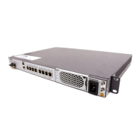
5.2.1 RHUB3908 Specifications
100 V AC to 120 V AC; 200 V AC to 240 V AC
Eight FE/GE electrical ports
Two FE/GE optical ports
8x90 W: A CPRI_E provides a power supply of 90 W.
 Loading...