17
7
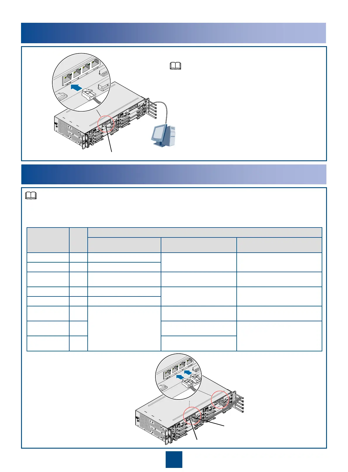
Connecting the External Clock/Time Cables
CLK
TOD
a. Making the external clock and time cables according to the pin definition table
b. Connecting the External Clock/Time Cables
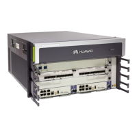
The interfaces CLK/TOD, CLK0/TOD0, and CLK1/TOD1 on the NE MPU use the same clock source and
clock cable. The NE08E-S6 with a CXPB board is used as an example here.
6
Connecting the Network Management Cable
NM
ETH/OAM
•The NMS cable is a serial cable and has
different pin arrangement than a common
network cable.
•For details about connecting a serial cable, see
the "Making a Serial Cable" in the
Installation
Guide
.
NOTE
NOTE
Color PIN Pin of the CLK and TOD Interfaces
120-hm external clock External time (1PPS + time
information)
External time (DCLS)
White/orange 1 Rx negative of external clock Not defined Not defined
Orange 2 Rx positive of external clock
White/green 3 Not defined RS422 input/output negative of
1PPS signals
RS422 input/output negative of DCLS
time signals
Green 4 Tx negative of external clock Grounding Grounding
Blue 5 Tx positive of external clock
White/blue 6 Not defined RS422 input/output positive of 1PPS
signals
RS422 input/output positive of DCLS
time signals
White/brown 7 RS422 input/output negative of
time information
Not defined
Brown 8 RS422 input/output positive of time
information
 Loading...