22
1
Installation Checklist
2
Checking Optical Power
Checking the Installation
No. Check Item
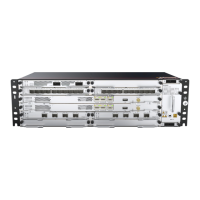
1 The cabinet is installed in the position specified in the engineering documents.
2
The cabinet components are installed correctly, without damaged or loosen parts. There are no fingerprints,
scratch marks, or other stains on the cabinet.
3 Cable outlets at the top and bottom of the cabinet are sealed.
4 Cables are routed according to the engineering documents.
5
Cables are not damaged or broken, there are no joints on cables, and cable connectors are inserted correctly
and firmly.
6
Information on cable/fiber labels is correct, clear, and neat.
7
The fibers routed outside the cabinet are placed in tubes or troughs and are not squeezed.
8
The bending radius of a single-mode G.657A2 optical fiber is greater than or equal to 10 mm, and the
bending radius of a multi-mode A1b optical fiber is greater than or equal to 30 mm. There are no sharp
components along the routing path of fibers.
9
Fibers are properly bound using fiber binding tape.
The following table describes comparison between the transmit optical power of 50 Gbps optical modules and
damaged optical power threshold at the receive end:
For applications of the 50 Gbps optical module supporting a distance of 40 km:
• 1. To ensure that the optical module runs stably for a long time, adjust the receive optical power of the optical module to
a value lower than -4 dB. According to the IEEE 802.3 standard, if the receive optical power of the optical module
exceeds -2.3 dB, the optical module may be permanently damaged.
Optical
Module Type
Maximum Average
Transmit Optical
Power
Minimum Average
Transmit Optical
Power
Damaged Optical
Power Threshold at
the Receive End
Description
50GBASE-LR
(10km)
4.2 -4.5 5.2
The damaged optical power
threshold is greater than the
maximum average transmit optical
power, posting low self-loop risks.
50GBASE-ER
(40km)
6.6 0.4 -2.4
The damaged optical power
threshold is 9dBm lower than the
maximum average transmit optical
power and 2.8dBm lower than the
minimum average transmit optical
power, posing high self-loop risks.
In this case, an optical attenuator
must be configured for self-loop.