EasyManua.ls Logo

Huawei NetEngine-8000-M8 User Manual

Huawei NetEngine-8000-M8
26 pages
To Next Page IconTo Next Page
Page #1 background imageLoading...
Page #1 background image
1
Precautions
This document provides quick guidelines for hardware installation.
This document does not describe pre-delivery assembly. This document pertains to onsite installation.
Electrostatic Discharge
Put on ESD gloves or an ESD wrist strap before handling plugboards, boards, and IC chips to prevent damage to
sensitive components caused by electrostatic discharge from the human body. Ensure that the other end of the
ESD wrist strap is properly grounded.
Binding Cables
The binding intervals between cable ties or fiber binding straps inside a cabinet must not exceed 250 mm.
The interval must not exceed 200 mm for user cables inside a cabinet.
If a cable trough passes two through beams, binding intervals between cable ties for all cables and
corrugated pipes outside a cabinet are determined by the distance between the two beams. If a cable trough
does not pass through beams, the binding interval between cable ties must not exceed 250 mm.
Pre-installation Check
Check that the equipment room, cabinet, power supply, ground cables, optical cables, and associated
facilities are all ready prior to installation.
This device is a class A product, which can only be installed indoors.
A product and may cause radio interference in a living environment. In this case, you may need to take
feasible measures for the radio interference.
Devices such as wireless antennas cannot be installed in the equipment room. If the devices must be
installed, they must be lower than the electromagnetic environment requirements (for details, see the
electromagnetic environment requirements) or add necessary electromagnetic shielding measures.
Installation Environment
The device does not have an air filter. It is recommended that the air filter be dustproof at the cabinet level.
Question and Answer IconNeed help?

Do you have a question about the Huawei NetEngine-8000-M8 and is the answer not in the manual?

Huawei NetEngine-8000-M8 Specifications

General IconGeneral
BrandHuawei
ModelNetEngine-8000-M8
CategoryNetwork Hardware
LanguageEnglish

Summary

Precautions

Electrostatic Discharge (ESD) Safety

Essential steps to prevent damage from static discharge to components.

Cable Binding and Management

Guidelines for cable tie intervals and proper cable management within cabinets.

Pre-Installation and Environment Checks

Ensures readiness of equipment room, power, and checks environmental suitability.

Board Handling Procedures

ESD Protection and Board Handling

Emphasizes ESD precautions like wrist straps and gloves before handling boards.

Correct Board Gripping and Insertion

Details proper techniques for holding ejector levers and inserting boards into slots.

Filler Panel Installation Requirements

Explains the necessity of installing filler panels for device functionality and protection.

Tools for Installation

Chassis Installation Introduction

Chassis Component Identification

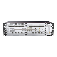
Illustrates and labels the main components of the chassis for identification.

Chassis Installation Requirements

Cabinet and Environment Specifications

Details required cabinet types (ETSI, 19-inch) and environmental considerations.

Heat Dissipation and Cabinet Loading Safety

Warns about heat dissipation capabilities and loading limits within the cabinet.

Mounting Ear Placement Guidance

Provides instructions on correct positioning of mounting ears for different cabinet types.

Installing Chassis in Standard 19-Inch Cabinet

Installing Chassis in ETSI Cabinet with Front Columns

Installing Chassis in ETSI Cabinet with Middle Columns

Installing Boards and Components

Board Installation Procedure

Details loosening screws, holding ejectors, inserting, and tightening screws for board installation.

Installing Fans and Power Boards

Fan Module Installation Caution

Highlights the need for proper alignment and insertion of the fan module.

Power Board Installation Caution

Emphasizes correct alignment and insertion, and not installing when powered on.

Installing Fibers and Cables

Common Cables Overview

Lists and illustrates common cables used with the chassis.

DC Power Cable Installation

Step-by-step guide for connecting the DC power cable to the PIU board.

DC Power Cable Routing and Safety

Power Cable Safety Warnings

Critical DANGER notices regarding electrical shock, proper connection, and cable bending.

Cable Routing and Labeling Guidelines

Recommendations for routing power and signal cables separately and labeling them.

Installing Service Cables

Ethernet Service Cable Limitations

Notes on limitations for shielded network cables in specific cabinet types.

E1 Service Cable Installation Advice

Recommendations for E1 cable placement and connector crimping.

Installing Chassis Fibers

Fiber Installation Safety and Best Practices

Includes warnings about optical ports, FOAs, bending radii, and connector protection.

Installing Fibers Outside Cabinet

Corrugated Pipe Fiber Capacity

Specifies the maximum number of fibers per corrugated pipe.

Corrugated Pipe Routing

General advice on routing corrugated pipes based on equipment room conditions.

Installing Network Management Cables

Network Management Cable Connection

Procedure for connecting network management cables to the ETH/OAM port.

Installing External Clock Cable

CLK/TOD/RS-485 Cable Connection

Guide for connecting the clock/TOD/RS-485 cable to the control board.

Installing External Alarm Cables

Alarm Cable Connection

Details the ALMI/ALMO port for alarm input and output connections.

Cable and Fiber Layout

Cable/Fiber Connection Diagrams

Illustrates the placement of various cables and fibers on the chassis.

Cable Routing for Fan Maintenance

Notes on routing power cables to avoid interfering with fan maintenance.

Cabinet Cable Layout

Cable Layout for Devices in Cabinet

Shows cable routing for the device and other equipment within the same cabinet.

Installation and Optical Power Checks

Installation Checklist

A comprehensive list of items to check after installation is complete.

Optical Power Verification

Compares transmit and receive optical power against thresholds for 50 Gbps modules.

Optical Link and Power Supply Checks

Optical Link Verification

Details using an OTDR meter to check optical link quality and cleanliness.

Power Supply Checks Before Power-On

Verifies external power supply voltage, fuse capacity, and input power.

Post-Power-On Indicator Checks

Indicator Statuses After Power-On

Describes normal and abnormal states for FAN/PWR indicators.

Board Indicator Status and Handling

Board Indicator Checks and Exception Handling

Details normal/abnormal states for STAT, PROG, SYNC indicators and how to handle issues.

Related product manuals