3 Link/Active
indicator of the GE
electrical port
4 Speed indicator of
the GE electrical
port
5 Interface module
handle
- -
Indicators
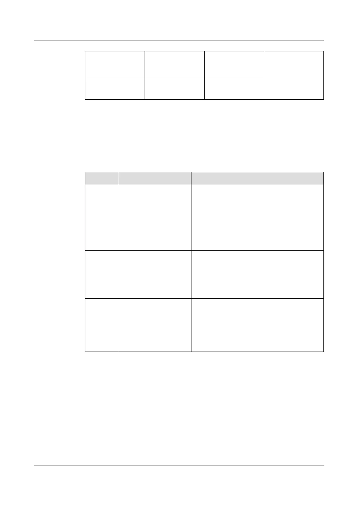
Table 4-7 describes indicators on a GE electrical interface module of a powered-on storage
system.
Table 4-7 Indicators on a GE electrical interface module
No.
Indicator Status and Description
1 Power indicator/Hot
Swap button on the
interface module
l Steady green: The interface module is
working correctly.
l Blinking green: There is a hot swap request to
the module.
l Steady red: The module is faulty.
l Off: The interface module is powered off or
hot swappable.
3 Link/Active indicator of
the GE electrical port
l Steady green: The link to the application
server is normal.
l Blinking green: Data is being transferred.
l Off: The link to the application server is down
or no link exists.
4 Speed indicator of the GE
electrical port
l Steady yellow: The data transfer rate between
the storage system and the application server
is 1 Gbit/s.
l Off: The data transfer rate between the storage
system and the application server is less than
1 Gbit/s.
4.2.2.8 10GE Electrical Interface Module
Function
A 10GE electrical interface module has four 10 Gbit/s electrical ports.
Ports
Figure 4-22 shows the appearance of a 10GE electrical interface module. 10GE electrical
interface modules of the storage system support GE/10GE autonegotiation.
OceanStor 2600 V3
Product Description
4 Hardware Architecture
Issue 09 (2019-05-15) Copyright © Huawei Technologies Co., Ltd. 36

 Loading...