S6720-30C-EI-24S-AC
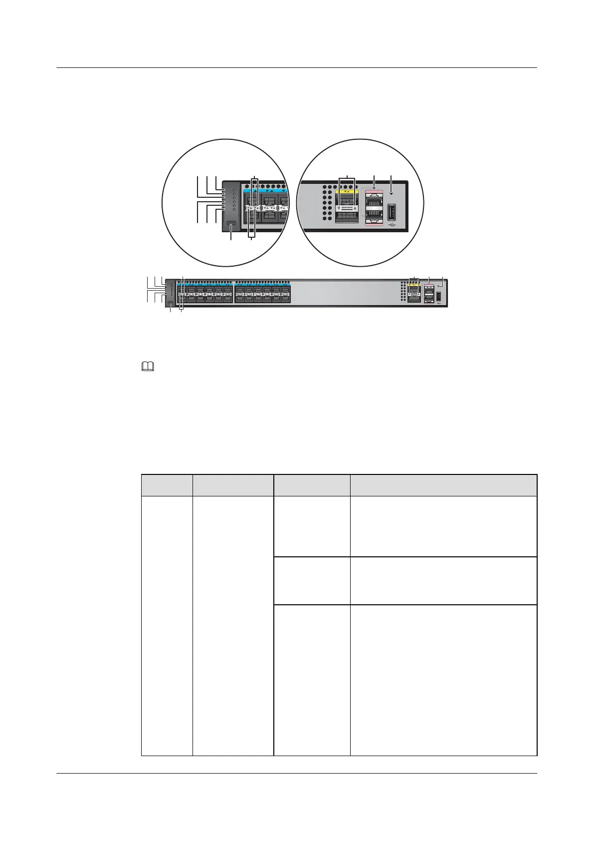
Figure 2-10 Indicators on the S6720-30C-EI-24S-AC
S6720-30C-EI-24S
12
123
4
567891011 12
13 14 15 16 17 18 19 20 21 22 23 24
CONSOLE
ETH
MODE
HUAWEI
STCK
SPED
STAT
SYS
PWR1
PWR2
S6720-30C-EI-24S
123
4
5
MODE
HUAWEI
STCK
SPED
STAT
SYS
PWR1
PWR2
1
7
23
654
8
8
NOTE
The S6720-EI series switches provide a command that can turn on the fault indicators to help field
maintenance personnel find a faulty switch.
The SYS indicator and mode indicators (STAT, SPED, and STCK) are used as fault indicators. When an
S6720-EI switch is faulty, you can run the command to turn on the fault indicators. Then the SYS indicator
and mode indicators fast blink red to help field maintenance personnel quickly find the faulty switch.
Table 2-14 Description of indicators on the switch
No. Indicator Color Description
1 PWR1: power
module indicator
- Off: No power module is available in
power module slot 1, or the switch has only
one power module but the power module
does not work normally.
Green Steady on: A power module is installed in
power module slot 1 and is working
normally.
Yellow Steady on: The switch has two power
modules installed. Any of the following
situations occurs in power module slot 1:
l A power module is available in this slot
but its power switch is in OFF position.
l A power module is available in this slot
but it is not connected to a power
source.
l The power module in this slot has
failed.
S6700 Series Ethernet Switches
Hardware Description 2 Chassis
Issue 12 (2015-07-31) Huawei Proprietary and Confidential
Copyright © Huawei Technologies Co., Ltd.
30

 Loading...