14
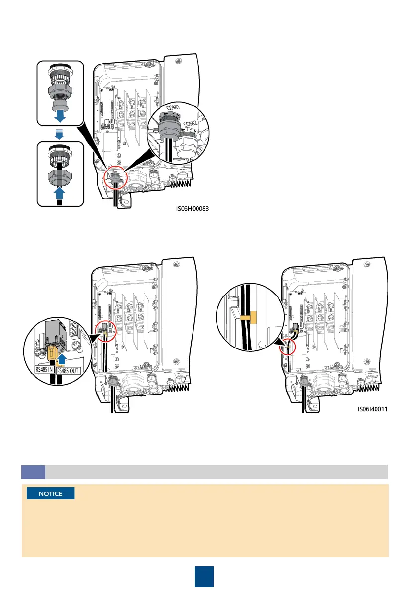
2. Route the cable through the cable gland.
3. Insert the RJ45 connector into the RJ45
network port in the SUN2000 maintenance
compartment.
4. Bind the communications cable.
5. Tighten the thread-lock sealing nut and seal the cable gland.
(Optional) Installing the Solar Tracker Power Cable
4.7
1. A switch-disconnector-fuse or fuse-switch-disconnector with a voltage of no less than 500 V,
current of 16 A, and protection type of gM needs to be installed between the SUN2000 and
the tracker controller for protection.
2. The cable between the wiring terminal on the power cable and the switch-disconnector-fuse
or fuse-switch-disconnector should be less than or equal to 2.5 meters.
 Loading...