10
Installing RS485 Communications Cables
4.6
The DJYP2VP2-22 2x2x1 computer cable or a communications cable with a cross-sectional area
of 1 mm
2
and outer diameter of 14–18 mm is recommended.
1. When routing communications cables, separate communications cables from power cables to
prevent communication from being affected.
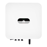
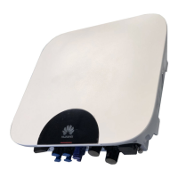
2. An RS485 cable can connect to either a terminal block or an RJ45 network port. It is
recommended that the RS485 cable connect to a terminal block.
Connecting to a terminal block (recommended)
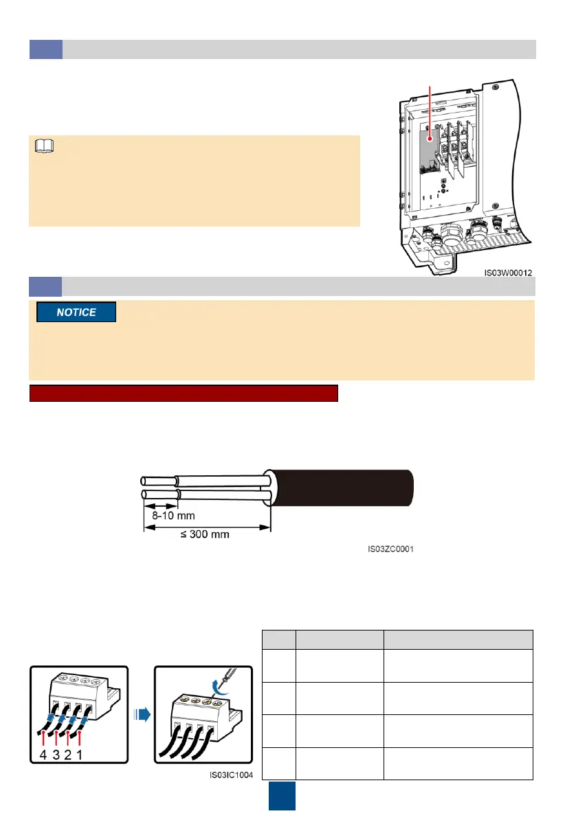
1. Remove an appropriate length of the jacket and core wire insulation layer from the
communications cable using a wire stripper.
2. Remove the locking caps from the COM1 and COM2 connectors at the SUN2000 bottom and
then remove the plugs from the caps.
3. Route the communications cables through the locking caps, and then the COM1 (RS485 IN)
and COM2 (RS485 OUT) connectors at the SUN2000 bottom.
4. Remove the terminal base from the terminal block, and connect the communications cables to
the terminal base.
–
Selecting a Communication Mode
4.5
1. If MBUS (PLC) is used, no RS485 communications cable is
required to connect to the SUN2000.
2. If RS485 is used, an RS485 communications cable needs to
connect to the SUN2000.
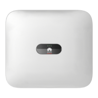
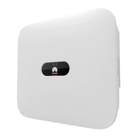
• The SUN2000 with no user interface board supports only
MBUS (PLC) communication mode.
• The SUN2000 with a user interface board supports MBUS
(PLC) and RS485 communication modes, but only one
communication mode can be selected at the time of setup.
Position for the user
interface board