4
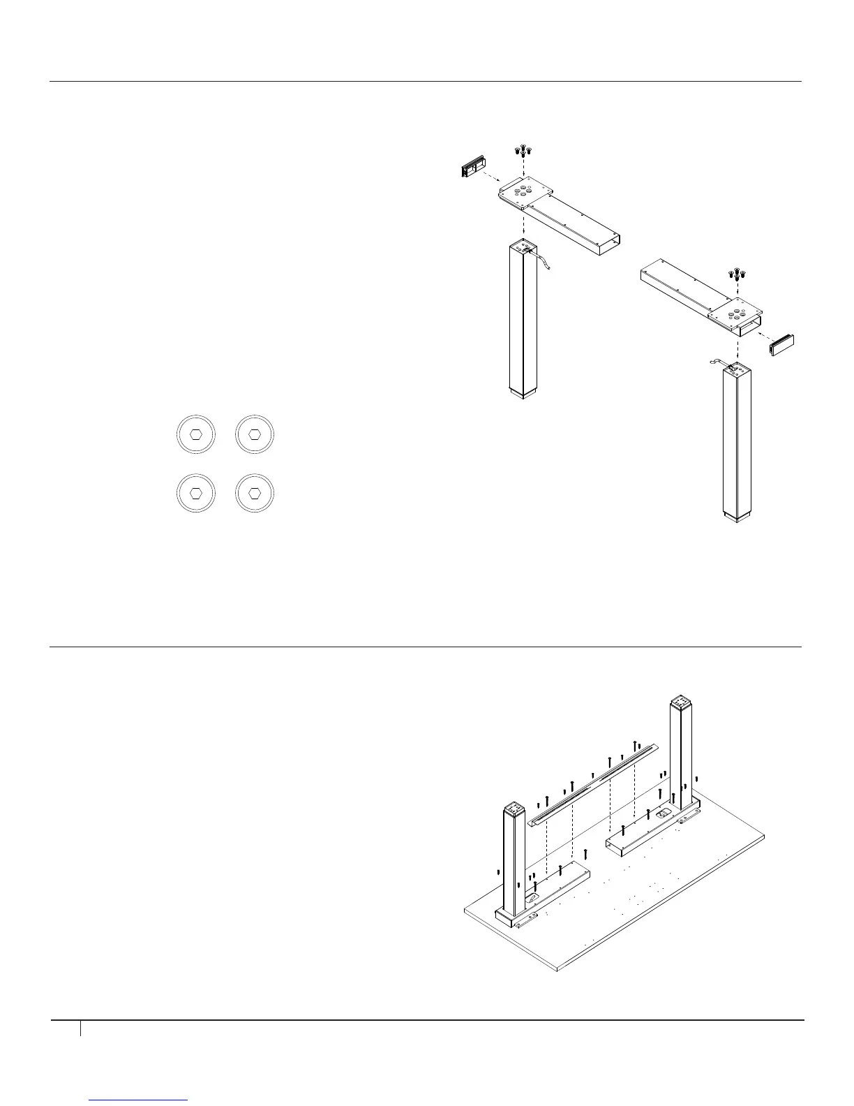
STEP 1
Assemble LEG to TOP FRAME section
Tools: 5 mm Hex Key
• Thread LEG MOTOR CABLE into TOP FRAME opening
followed by top of LEG until LEG rests flat against TOP
FRAME mounting plate. Attach LEG to TOP FRAME using (4)
M8 x 20 mm Flat Head Socket Screws.
• Screws should be tightened in diagonal order (fig. A). Repeat
this pattern after all 4 screws are in place to ensure a tight fit.
Screws should not be tightened beyond 15 N-m of torque.
• Insert END CAP into the Top Frame opening as shown.
• Repeat actions for remaining LEG, END CAP, and TOP
FRAME section.
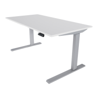
STEP 2 (IF USING HUMANSCALE WORK SURFACE)
Assemble TOP FRAME to WORK SURFACE
Tools: #2 Phillips Screwdriver
• Place WORK SURFACE on floor, top down, so that the pilot
holes are visible. Line up TOP FRAME with pilot holes.
• Place the SUPPORT BAR as pictured, in the back of the work
surface, so that its slots are aligned with the holes on the TOP
FRAME.
• Use 4 (#5 x 55 mm Flange Head Wood-Screw) screws to
fasten the SUPPORT BAR to the TOP FRAME, use 5
(5 x 18mm Flange Head Wood-Screw) to fasten the opposite
flange of the SUPPORT BAR to the WORK SURFACE.
• Use remaining #5 x 25 mm Flat Countersunk Head
Woodscrews and #5 x 55 mm Flange Head Wood Screws to
complete attaching the TOP FRAME to the WORK SURFACE.
fig. A
1
2
3
4