5
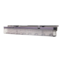
STEP 4 (IF USING HUMANSCALE WORK SURFACE)
Mount SMART CONTROLLER
Tools: #2 Phillips Screwdriver
• Line up SMART CONTROLLER with pilot holes and attach
to WORK SURFACE using (2) #4.5 x 20 mm Pan Head
Wood Screws.
Mount ANALOG TOUCHPAD (if specified)
Tools: #2 Phillips Screwdriver
• Line up ANALOG TOUCHPAD with pilot holes and attach to
WORK SURFACE using (2) #4.5 x 20 mm Pan Head Wood
Screws.
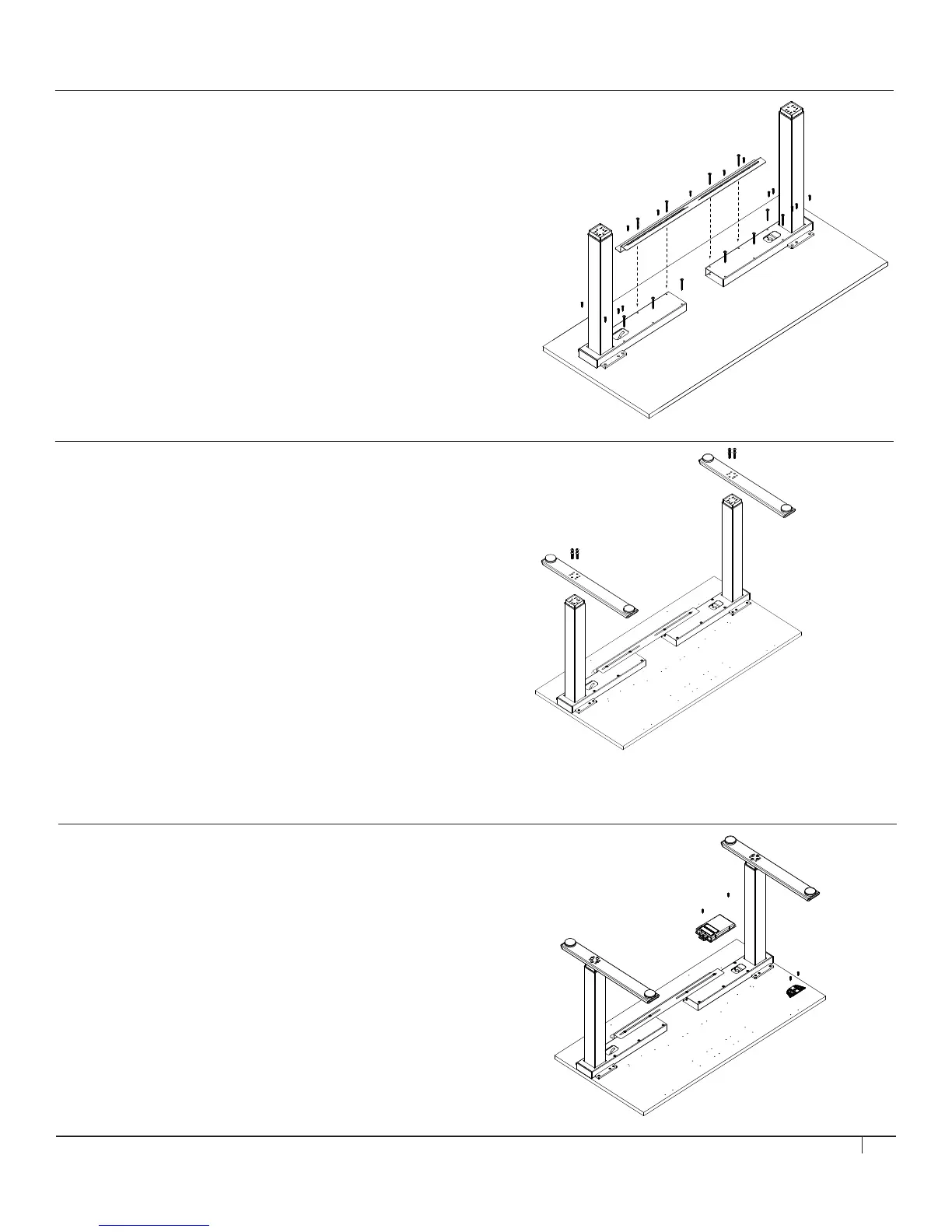
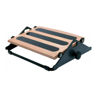
STEP 3
Assemble FOOT to LEG
Tools: 6 mm Hex Key
• Attach FOOT to LEG using (4) M8 x 35 mm Button Head Socket
Screws. Make sure FOOT is oriented so that its front and back edges
line up with the front and back edges of the WORK SURFACE. Repeat
action for remaining FOOT and LEG.
Screws should not be tightened beyond 15 N-m of torque.
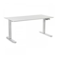
STEP 2 (IF USING A NON-HUMANSCALE WORK SURFACE)
Assemble TOP FRAME to WORK SURFACE
Tools: #2 Phillips Screwdriver
• For Work Surfaces that are 30” deep: Measure and mark 16.5”
from the front edge of the work surface to the front edge of the top
frame.
• For Work Surfaces that are 24” deep: Measure and mark 13.5”
from the front edge of the work surface to the front edge of the top
frame.
• For ALL eFloat models: The maximum surface width is 72”.
Do not exceed a width of 56.25” when measuring from outside
of leg to outside of leg.