6
STEP 4 (IF USING A NON-HUMANSCALE WORK SURFACE)
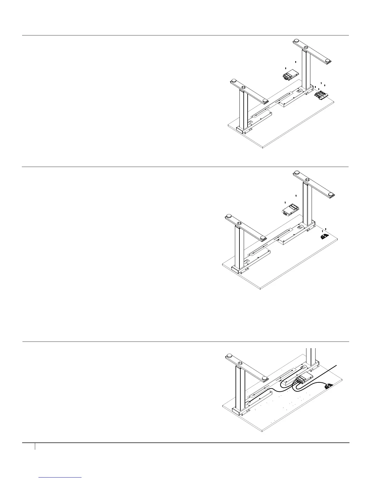
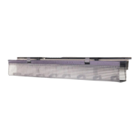
Mount SMART CONTROLLER
Tools: #2 Phillips Screwdriver
• Place SMART CONTROLLER on the underside of the surface in an
area where power cable, leg motor cables and touchpad cable can be
conveniently installed. Ensure that installation of SMART CONTROLLER
will not interfere with additional components to be installed. Attach to
WORK SURFACE using (2) #4.5 x 20 mm Pan Head Wood Screws.
Mount ANALOG TOUCHPAD (if specified)
Tools: #2 Phillips Screwdriver
• Install the ANALOG TOUCHPAD to the right or left side of the WORK
SURFACE using (2) #4.5 x 20 mm Pan Head Wood Screws.
Mount ANALOG TOUCHPAD (if specified)
Tools: #2 Phillips Screwdriver
• Install the DIGITAL TOUCHPAD to the right or left side of the
WORK SURFACE using (4) #4.5 x 20 mm Pan Head Wood Screws.
STEP 5
Attach ALL CABLES to CONTROLLER
• Connect LEFT LEG MOTOR CABLE to M1 slot on SMART
CONTROLLER and connect RIGHT LEG MOTOR CABLE to
M2 slot on SMART CONTROLLER. (fig. B)
• Plug TOUCHPAD CABLE into SMART CONTROLLER. (fig. C)
• Plug female end of POWER CABLE into SMART CONTROLLER. (fig. D)
STEP 4 (IF USING HUMANSCALE WORK SURFACE - CONT.)
Mount DIGITAL TOUCHPAD (if specified)
Tools: #2 Phillips Screwdriver
• Line up DIGITAL TOUCHPAD with pilot holes and attach to WORK
SURFACE using (4) #4.5 x 20 mm Pan Head Wood Screws. Please note
that only the two forward holes are pre-drilled and the two back holes are
not pre-drilled.
fig. B
fig. C
fig. D