Do you have a question about the Humminbird 718 and is the answer not in the manual?
Explains the 200/83 kHz DualBeam PLUS™ sonar system with 60° coverage.
Describes the QuadraBeam PLUS™ sonar with 90° coverage and side beams.
Details the WideSide® sonar with three beams for side and down looking.
Explains Universal Sonar 2 compatibility with Minnkota trolling motors.
Explains the 3D representation and temporal nature of sonar data display.
Details the RTS Window, its narrow and wide modes, and how it displays sonar intensity.
Explains how to pause the sonar display and use a cursor to analyze returns.
Describes how bottom contours are displayed and how to interpret bottom hardness.
Explains different display modes for bottom and structure representation.
Presents a historical log of sonar returns, showing depth, speed, and temperature.
Provides a magnified view of the bottom and structure for better detail.
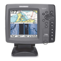
Displays sonar returns from 83 kHz and 200 kHz beams side-by-side.
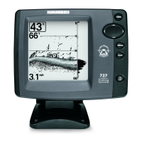
Displays digital data in a large, easy-to-see format, ideal for quick reading.
Displays Real Time Sonar data in a traditional flasher format.
Displays sonar data from left, right, and down beams for wider coverage.
Displays information from the 455 kHz WideSide® transducer for side-looking sonar.
Identifies the screen and primary buttons like VIEW, MENU, and EXIT.
Explains powering the unit on/off and adjusting backlight/contrast.
Details the functions of the VIEW key for cycling views and the MENU key for accessing menus.
Describes the 4-WAY Cursor Control key and VIEW PRESET keys for navigation and saving views.
Explains the multiple uses of the EXIT key for navigation and alarm cancellation.
Describes using the system for on-the-water operation with a connected transducer.
Explains using the simulator for learning system operation before going on the water.
Guides on viewing system connections and performing a unit self-test.
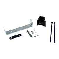
Lists accessories connected to the system for verification.
Explains how to update system software using a PC Connect cable.
Guides on selecting startup modes like Normal, Simulator, System Status, or PC Connect.
Introduces the X-Press™ Menu as a shortcut to frequently-used settings based on the current view.
Explains the Main Menu structure with tabbed headings for settings.
Explains how to switch between Normal and Advanced modes to simplify or expand menu options.
Details alarm settings like Depth, Fish ID, and Low Battery alarms.
Details the settings available within the Sonar tab of the Main Menu.
Covers unit settings like units of measure, user mode, language, and time.
Allows setting available views to hidden or visible in the view rotation.
Displays additional menu choices that support attached accessories.
Steps to take if the fishing system fails to power on.
Addresses issues where the system defaults to simulator mode despite a connected transducer.
Covers issues like power loss at high speeds or weak bottom readings.
Explains how to identify sources of electrical or hydrodynamic noise interference.
Purchase and connect for specialized QuadraBeam PLUS™ functions and wide coverage.
Obtain barometric pressure and trend data in real time.
Connect a handheld or other NMEA GPS-compatible device.
Receive remote sonar signals from a SmartCast® Remote Sonar Sensor.
Connect to a PC to upload software updates and new features.
Supports integrated transducer built into Minnkota trolling motors.
Defines how bottom contours are represented and interpreted on the display.
Explains advanced processing to identify and display fish symbols.
Describes unintentional sound waves that interfere with sonar operation.
Explains the component that converts electrical energy to sound energy and vice-versa.
| Display Size | 5 inches |
|---|---|
| Display Type | Color LCD |
| GPS | No |
| Target Separation | 2.5 inches |
| Chartplotting | No |
| Waterproof Rating | IPX7 |
| Sonar Frequency | 200 kHz |
| Max Depth | 1500 feet |
| Transducer Type | Dual Beam |
| Sonar Coverage | 20° / 60° |
| Sonar Type | DualBeam |
| Display Pixel Matrix | 320 x 320 pixels |