1
532405-5_A
HELIX® SERIES CONTROL HEAD Installation Guide
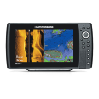
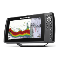
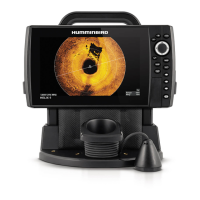
Follow the instructions in this installation guide to gimbal mount the control head.
I P
Read the instructions in this transducer guide completely to understand the mounting guidelines before starting the installation.
Visit our Web site at humminbird.com for additional information and resources for transducer installations. Also, visit
youtube.com/humminbirdtv for informational videos.
Supplies: In addition to the hardware supplied with your control head, you will need a powered hand drill and various drill bits, Phillips
head screwdriver, flat head screwdriver, pencil, safety glasses and dust mask, marine-grade silicone sealant, dielectric grease
(optional), extension cables (optional), Ethernet cables (optional), and accessory cables (optional). Also, see Connect Power to
determine the type of connection, fuse size, and additional equipment you will need for the installation.
Accessories and Ethern
et: Accessories and Ethernet equipment are available for purchaseThe installation guides are available
with the product, or they can be downloaded from our Web site.
I O
1
|
Plan the Mounting Location
1. Place 1 rubber washer onto each gimbal knob.
2. Install the gimbal knobs (with washers) into each side of the control head. Tighten the knobs just enough so you can slide the control
head into the gimbal bracket arms.
Assembling the Control Head and Bracket
gimbal
knob
bracket arm
rubber
washer
NOTE: If you prefer to mount the control head overhead, flip the bracket to the top of the control head. The opening in the gimbal bracket arms
must face the rear of the control head.
3. Place the assembled control head in various locations to determine the best mounting location with the following requirements:
Δ a stable, protected surface to protect the control head from excessive wave shock, vibration, and water
Δ sufficient space for the control head tilt range
Δ visibility during operation, as well as easy installation and removal
Δ access above and below the mounting surface to pass the cables through to the control head
Δ space for the 1" (25 mm) cable hole located 2" to 4" (50 to 100 mm) behind the chosen mounting location
4. Test route all cables (transducer, power, Ethernet, accessories) to the control head mounting location. Leave enough cable length for
installing the cable tray and for the control head tilt range.
5. After you have selected the mounting location, loosen the gimbal knobs and remove the control head from the gimbal bracket.
