© 2005 Hunter Fan Company 41860-01 02/24/2005
55
55
5
FF
FF
F
ii
ii
i
gg
gg
g
urur
urur
ur
e 8 - Ie 8 - I
e 8 - Ie 8 - I
e 8 - I
nn
nn
n
ss
ss
s
ee
ee
e
rr
rr
r
tt
tt
t
inin
inin
in
g tg t
g tg t
g t
hh
hh
h
e ie i
e ie i
e i
ss
ss
s
oo
oo
o
ll
ll
l
aa
aa
a
tt
tt
t
oo
oo
o
rr
rr
r
s ins in
s ins in
s in
tt
tt
t
o to t
o to t
o t
hh
hh
h
e ce c
e ce c
e c
ee
ee
e
ilinilin
ilinilin
ilin
g pg p
g pg p
g p
ll
ll
l
aa
aa
a
tt
tt
t
ee
ee
e
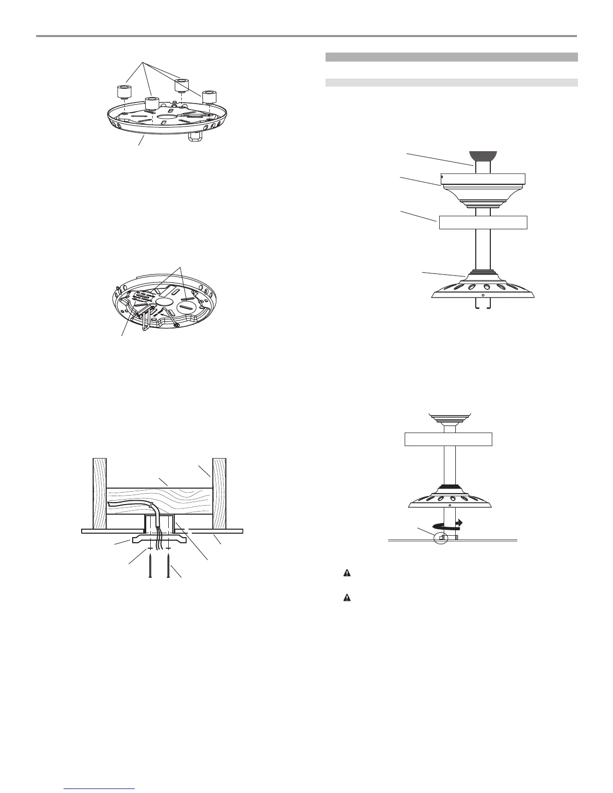
4. Align the slotted holes (refer to Figure 9) in the ceiling plate
with the pilot holes in the wood support structure. Note: The
isolation pads should be flush against the ceiling.
For Angled Ceilings: Be sure to orient the ceiling plate so that
the arrows on the ceiling plate are pointing towards the ceiling
peak. Refer to Figure 9.
FF
FF
F
ii
ii
i
gg
gg
g
urur
urur
ur
e 9 - Le 9 - L
e 9 - Le 9 - L
e 9 - L
oo
oo
o
cc
cc
c
aa
aa
a
tt
tt
t
inin
inin
in
g tg t
g tg t
g t
hh
hh
h
e se s
e se s
e s
ll
ll
l
oo
oo
o
tt
tt
t
tt
tt
t
ee
ee
e
d hd h
d hd h
d h
oo
oo
o
ll
ll
l
ee
ee
e
s ts t
s ts t
s t
o uo u
o uo u
o u
ss
ss
s
ee
ee
e
5. Place a flat washer on each of the two 3" screws and pass the
screws through the slotted holes in the ceiling plate as shown
in Figure 10.
6. Tighten the screws into the 9/64" pilot holes; do not use lubri-
cants on the screws. Do not overtighten.
FF
FF
F
ii
ii
i
gg
gg
g
urur
urur
ur
e 10 - Ie 10 - I
e 10 - Ie 10 - I
e 10 - I
nn
nn
n
ss
ss
s
tt
tt
t
aa
aa
a
llinllin
llinllin
llin
g tg t
g tg t
g t
hh
hh
h
e ce c
e ce c
e c
ee
ee
e
ilinilin
ilinilin
ilin
g pg p
g pg p
g p
ll
ll
l
aa
aa
a
tt
tt
t
ee
ee
e
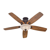
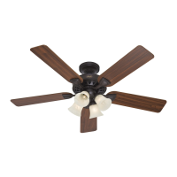
assembling the fan
installing the downrod
1. Insert the downrod through the canopy, the canopy trim ring,
the adapter cover as shown in Figure 11.
Figure 11 - Installing the downrod
2. Feed the wires from the fan through the downrod.
3. Screw the downrod into the fan until tight.
4. Tighten the allen head set screw on the adapter as shown in
Figure 12.
Figure 12 - Installing the downrod
WW
WW
W
AA
AA
A
RR
RR
R
NN
NN
N
II
II
I
NN
NN
N
G: FG: F
G: FG: F
G: F
aa
aa
a
ilurilur
ilurilur
ilur
e te t
e te t
e t
o so s
o so s
o s
ee
ee
e
cc
cc
c
urur
urur
ur
ee
ee
e
ll
ll
l
y ty t
y ty t
y t
ii
ii
i
gg
gg
g
hh
hh
h
tt
tt
t
ee
ee
e
n tn t
n tn t
n t
hh
hh
h
e se s
e se s
e s
ee
ee
e
t st s
t st s
t s
cc
cc
c
rr
rr
r
ee
ee
e
w ow o
w ow o
w o
nn
nn
n
tt
tt
t
hh
hh
h
e ae a
e ae a
e a
dd
dd
d
aa
aa
a
pp
pp
p
tt
tt
t
ee
ee
e
r cr c
r cr c
r c
oo
oo
o
ulul
ulul
ul
d cd c
d cd c
d c
aa
aa
a
uu
uu
u
ss
ss
s
e te t
e te t
e t
hh
hh
h
e fe f
e fe f
e f
aa
aa
a
n tn t
n tn t
n t
o fo f
o fo f
o f
aa
aa
a
ll.ll.
ll.ll.
ll.
CC
CC
C
AA
AA
A
UU
UU
U
TT
TT
T
II
II
I
OO
OO
O
N: TN: T
N: TN: T
N: T
hh
hh
h
e de d
e de d
e d
oo
oo
o
ww
ww
w
nrnr
nrnr
nr
oo
oo
o
d hd h
d hd h
d h
aa
aa
a
s a ss a s
s a ss a s
s a s
pp
pp
p
ee
ee
e
cc
cc
c
ii
ii
i
aa
aa
a
l cl c
l cl c
l c
oo
oo
o
aa
aa
a
tt
tt
t
inin
inin
in
g og o
g og o
g o
n tn t
n tn t
n t
hh
hh
h
ee
ee
e
tt
tt
t
hrhr
hrhr
hr
ee
ee
e
aa
aa
a
dd
dd
d
ss
ss
s
. D. D
. D. D
. D
o no n
o no n
o n
oo
oo
o
t rt r
t rt r
t r
ee
ee
e
mm
mm
m
oo
oo
o
vv
vv
v
e te t
e te t
e t
hh
hh
h
ii
ii
i
s cs c
s cs c
s c
oo
oo
o
aa
aa
a
tt
tt
t
inin
inin
in
g; tg; t
g; tg; t
g; t
hh
hh
h
e ce c
e ce c
e c
oo
oo
o
aa
aa
a
tt
tt
t
inin
inin
in
g pg p
g pg p
g p
rr
rr
r
ee
ee
e
vv
vv
v
ee
ee
e
nn
nn
n
tt
tt
t
ss
ss
s
tt
tt
t
hh
hh
h
e de d
e de d
e d
oo
oo
o
ww
ww
w
nrnr
nrnr
nr
oo
oo
o
d fd f
d fd f
d f
rr
rr
r
oo
oo
o
m unm un
m unm un
m un
ss
ss
s
cc
cc
c
rr
rr
r
ee
ee
e
ww
ww
w
inin
inin
in
gg
gg
g
. O. O
. O. O
. O
nn
nn
n
cc
cc
c
e ae a
e ae a
e a
ss
ss
s
ss
ss
s
ee
ee
e
mbmb
mbmb
mb
ll
ll
l
ee
ee
e
d, dd, d
d, dd, d
d, d
o no n
o no n
o n
oo
oo
o
tt
tt
t
rr
rr
r
ee
ee
e
mm
mm
m
oo
oo
o
vv
vv
v
e te t
e te t
e t
hh
hh
h
e de d
e de d
e d
oo
oo
o
ww
ww
w
nrnr
nrnr
nr
oo
oo
o
d.d.
d.d.
d.
Isolators
Ceiling Plate
Slots
Arrows for Orienting
on Angled Ceiling
Ceiling Joist
2 x 4 Brace
Ceiling
Ceiling Plate
Flat Washer
Outlet Box
3" Wood Screw
Canopy
Downrod
Canopy
Trim Ring
Adapter Cover
Allen Head
Set Screw