© 2005 Hunter Fan Company41860-01 02/24/2005
77
77
7
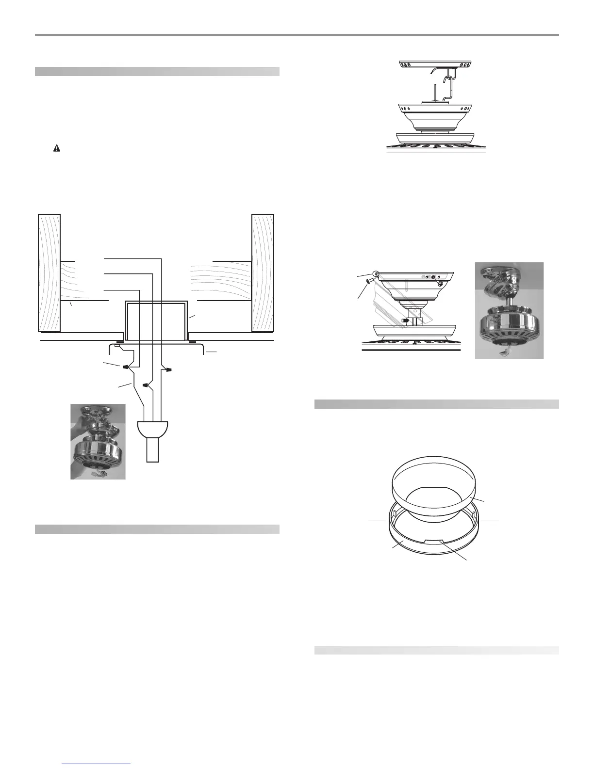
wiring the fan
1. Disconnect the power by turning off the circuit breakers to
the outlet box and associated wall switch location.
2.Connect the wires as shown in Figure 15. To connect the wires,
twist the bare metal leads together. Place a wire nut over the
intertwined length of wire and twist clockwise until tight.
CC
CC
C
AA
AA
A
UU
UU
U
TT
TT
T
II
II
I
OO
OO
O
N: BN: B
N: BN: B
N: B
e se s
e se s
e s
urur
urur
ur
e ne n
e ne n
e n
o bo b
o bo b
o b
aa
aa
a
rr
rr
r
e we w
e we w
e w
irir
irir
ir
e oe o
e oe o
e o
r wr w
r wr w
r w
irir
irir
ir
e se s
e se s
e s
tt
tt
t
rr
rr
r
aa
aa
a
nn
nn
n
dd
dd
d
s as a
s as a
s a
rr
rr
r
e ve v
e ve v
e v
ii
ii
i
ss
ss
s
--
--
-
ibib
ibib
ib
ll
ll
l
e ae a
e ae a
e a
ff
ff
f
tt
tt
t
ee
ee
e
r mr m
r mr m
r m
aa
aa
a
kk
kk
k
inin
inin
in
g cg c
g cg c
g c
oo
oo
o
nnnn
nnnn
nn
ee
ee
e
cc
cc
c
tt
tt
t
ii
ii
i
oo
oo
o
nn
nn
n
ss
ss
s
..
..
.
AA
AA
A
ll wll w
ll wll w
ll w
irir
irir
ir
inin
inin
in
g mug mu
g mug mu
g mu
ss
ss
s
t bt b
t bt b
t b
e in ae in a
e in ae in a
e in a
cc
cc
c
cc
cc
c
oo
oo
o
rr
rr
r
dd
dd
d
aa
aa
a
nn
nn
n
cc
cc
c
e we w
e we w
e w
ii
ii
i
tt
tt
t
h nh n
h nh n
h n
aa
aa
a
tt
tt
t
ii
ii
i
oo
oo
o
nn
nn
n
aa
aa
a
l al a
l al a
l a
nn
nn
n
d ld l
d ld l
d l
oo
oo
o
cc
cc
c
aa
aa
a
ll
ll
l
ee
ee
e
ll
ll
l
ee
ee
e
cc
cc
c
tt
tt
t
rr
rr
r
ii
ii
i
cc
cc
c
aa
aa
a
l cl c
l cl c
l c
oo
oo
o
dd
dd
d
ee
ee
e
s as a
s as a
s a
nn
nn
n
d Ad A
d Ad A
d A
NN
NN
N
SS
SS
S
I/NI/N
I/NI/N
I/N
FF
FF
F
PP
PP
P
A 70. IA 70. I
A 70. IA 70. I
A 70. I
f yf y
f yf y
f y
oo
oo
o
u au a
u au a
u a
rr
rr
r
e une un
e une un
e un
ff
ff
f
aa
aa
a
mm
mm
m
iliili
iliili
ili
aa
aa
a
rr
rr
r
ww
ww
w
ii
ii
i
tt
tt
t
h wh w
h wh w
h w
irir
irir
ir
inin
inin
in
gg
gg
g
, y, y
, y, y
, y
oo
oo
o
u su s
u su s
u s
hh
hh
h
oo
oo
o
ulul
ulul
ul
d ud u
d ud u
d u
ss
ss
s
e a qe a q
e a qe a q
e a q
uu
uu
u
aa
aa
a
lili
lili
li
ff
ff
f
ii
ii
i
ee
ee
e
d ed e
d ed e
d e
ll
ll
l
ee
ee
e
cc
cc
c
tt
tt
t
rr
rr
r
ii
ii
i
cc
cc
c
ii
ii
i
aa
aa
a
nn
nn
n
..
..
.
FF
installing the canopy
1. Rotate the fan 180º clockwise from the initial position when
hanging the fan. The arrows on the hanger ball and on the
ceiling plate should be pointing in the same direction and
should be pointing towards the tab hole on the canopy. Refer
to Figure 16.
2. Hook the tab hole over the tab on the ceiling plate as shown in
Figure 17.
3. Raise the canopy, be sure the holes in the canopy and the ceil-
ing plate are aligned, and loosely assemble the canopy screws
one at a time. When all three screws are assembled, securely
tighten all three canopy screws. Refer to Figure 17.
installing the canopy trim ring
1. To easily install the canopy trim ring, locate the two tabs on
the canopy trim ring. See Figure 18.
2. Take both hands and push the canopy trim ring up to the top
of the canopy. See Figure 18.
3. The canopy trim ring will snap and lock into place on the
canopy.
removing the canopy trim ring
1. Locate the tab indicators, small bumps on top of tabs. Refer to
Figure 19.
2. To remove the canopy trim ring, press firmly on opposite sides
of the ring towards the canopy as shown in Figure 19. The tabs
will flex out releasing the trim ring from the canopy.
Tab Hole
and Tab
Canopy
Screw
Power
Wires
in
Ceiling
Black
White
Bare or Green
2 x 4 Brace
Outlet Box
Ceiling Plate
Approved
Connectors
Green Ground Wire from
Hanger Pipe
White
Black
Canopy
Canopy
Trim Ring Tab
Press Here when
Removing
Press Here when
Removing